AutoRef distance violation checking
Distance violation checking is an element of the implementation for the AutoRef autonomous referee for RoboCup Middle Size League (MSL) robot soccer. The design of distance violation checking was contributed by AutoRef MSD 2020.
Introduction
Objective statement
The main objective of the implementation part of the project was to detect violations of the rules related to the distance between the ball and players during the following game states:
- Free kick
- Kick-off
- Corner kick
- Goal kick
- Throw-in
- Dropped-ball
- Penalty kick
These rules are described in laws number 8, 10, 13, 14, and 15 of the MSL Rulebook.
Motivation
This objective was chosen due to several reasons:
- Past projects analysis has shown that this functionality has never been designed before
- Stakeholder interviews (the MSL referees) had the conclusion that this kind of rules are hard to control for a human being
- Proof of concept for the developed functional specification was desirable
- Learning goals of the team members correspond to the technical solutions necessary for the functionality development
Scope of work
The following topics were included in the implementation scope:
- Requirements formulation
- Architectural decomposition development
- Individual code blocks development
- Integration of individual code blocks
- Software testing on the simulated images and videos
These topics are explained in detail in the following sections.
Process model
Introduction
The development activities of the design team need support from process models. In this project, the V-model is chosen to guide the development procedure from requirement engineering to system validation. Due to the particularity of the project itself, some details of the model have been changed. At the same time, the agile approach was used during system development and combined with the traditional V-model, which makes the project's progress more flexible and efficient.
Use of V-model
V-model has the following advantages for the development of the project:
- Design team's project is based on machine vision and software algorithms. V-model was first proposed in the software development environment and has matured in the software development field.
- The project team has five members, all of whom can participate in the development of subsystems and they can be developed at the same time. On the premise that the system architecture is determined, V-model can greatly improve the development efficiency.
- The system development starts from the fourth week, which means that the team needs to complete the system development in five weeks, and the mature and ready-to-use V-model process can save a lot of time that can be spent on the project management.

Based on the general V-model, a detailed test plan has been made for the verification of the system both from functional and performance perspectives.
Based on the requirements derivation results, functional and performance requirements were set up and related tests were planned as shown in the figure above. In this plan, the details of the V-model are supplemented, and more detailed test steps and iterations are added in the test and verification phases. The technical blocks were integrated into the first phase, then several images regarding typical use cases are created from the simulation environment (refer to Section 3) in order to verify the functional requirements. Videos were created to test the performance of the system based on particular scenarios (refer to Section 4). Code was updated iteratively after several tests. After the code was verified, a simulated game video was created in the simulation environment to illustrate how the system works in the 'real' world.
Agile approach
Due to the limited project time and various uncertainties in the system development process, Agile approach was applied in the system development process, which is mainly reflected in the system architecture and design choice part.
There are two main difficulties in the development of this project:
- How to implement an efficient and fast detection algorithm?
- How to achieve an accurate image capture in reality?
Usually, the algorithm needs to be executed after the system obtains the image, but it is worth noting that the design of vision system has the following two considerations, which greatly increases the complexity of the system design:
- Fixed camera OR moving camera
- One camera OR multiple cameras
After careful evaluation, we thought that the amount of time spent on the algorithm development will be greatly reduced in the design of the vision system, which is not the desired result. Therefore, we finally determined the system development scheme based on the agile method. In which, a single fixed camera is initially used, and a simulated game situation has been created under the software simulation environment as a reference sample for algorithm development. Optimization of the vision system can be carried out after the algorithm is developed.
The main idea is designing and checking the performance of the developed algorithm, which also confirms the rationality of ‘decision fast’ in the agile approach.
Major design choices
Programming language
MATLAB was chosen as the programming language due to the availability of in-built functions and documentation, which is useful in a quick test of a proof-of-concept of the implemented algorithm.
Selection of test environment
It was decided to use a simulation environment, to quickly test and verify the functionality of the ball-player distance violation check algorithm. It was desirable to verify the implementation in a simulation environment before committing to a specific choice of hardware. Other factors leading to the choice of a simulation environment include:
- Time limitations
- Limited access to the tech-united playing field (covid restrictions)
- Limited availability of match video footage with the desirable qualities (RGB top-view).
A custom simulation environment was built using MATLAB, Simulink 3D animation, and the Virtual Reality Modelling Language (VRML). Another option was to use GreenField, the visualization software used by Tech United in replaying recorded match data. This was not done due to less familiarity with Linux systems in the team, and a potential dependency on Tech-united developers, which could lead to a time-consuming learning curve.
Vision system parameters
The main design choices to be made were regarding the selection of the vision system, involving the following aspects:
- Mobility of the camera(s) (static vs moving)
- Location(s) of the camera(s)
- Camera resolution
Motivations for choosing a static camera were as following:
- Simplified localization requirements
- Simplified implementation architecture
- Less risk of invasiveness (spatial and audio)
Motivations for selecting a top camera view were as following:
- Using a top-view camera, projection errors can be minimized, which makes the implementation easier
- Having a movable top view camera that stays right above the ball would help avoid perspective distortions to a greater extent, but:
- We would need to account for localization uncertainty in the case of drones
- Multiple cameras might still be needed to detect events that are not in the vicinity of the ball
- It would be possible to view the entire field using a camera of sufficient height or field of view
Parameters to consider when using a top-view camera:
- Mounting height
- Field of View
- Resolution or Image size
Parameters to consider for the ball-player distance violation decision-making algorithm:
- Pixel to meter ratio or Resolution
- Frequency rate—The frequency rate required for the decision-making algorithm is defined based on
- The pixel-meter ratio,
- Worst-case scenarios defined considering robot dimensions, speed, and acceleration limits
- Maximum allowed perspective distortion
- When using a single top camera, perspective distortions are unavoidable
- High distortions can affect the visibility of the ball, separation of team players, and also lead to incorrect position estimate of the players.
Possible issues of using a single static top camera
- Perspective distortions
- Objects that are not directly below the camera would be seen at an oblique angle
- Occlusions
- The ball may not be completely visible and be occluded by players
- Players that are too close to each other may not be detected separately using a simple camera
- Limitations on accuracy
- Placing the camera very high above the field, in such a way that the entire field is visible, could lead to objects being very small in the images, and affect the accuracy of detections
- Going with a higher resolution camera would improve the accuracy of the field
Final decision:
Considering time limitations, and the implementation complexity related to the use of multiple cameras and moving cameras, a decision was made to test the ball-player distance violation algorithm for a single top camera concept. The camera was considered to be at a height of 12 m above the center of the field and facing downwards. A choice was also made to keep the field of view to a manageable value of 1.2 radians, such that perspective distortions are minimized. Meanwhile, to have a manageable resolution, the images taken were considered to be Full HD (1920 x 1080) RGB images.
Requirements
There are different kinds of requirements, that are explained in the following sections.
Functional requirements
Formal formulation:
The first and foremost sub-requirement is that the system must be modular. Other sub-requirements are as follows:
- The system must detect the players and the ball inside the soccer field boundaries and identify the players’ team.
- The system must detect the different zones inside the soccer field (corner area, penalty area, etc.)
And the main requirements are:
- The system must check if the distance between the center of the ball and any part of the attacker team members (except for the kicker) before free kick, corner kick, kick-off, goal kick, and throw-in is not less than 2m (with acceptable 5cm inaccuracy). One of the robots may stay anywhere inside the penalty area (except for the goal area) of its own team, even if the distance to the ball is shorter than 2m.
- The system must check if the distance between the center of the ball and any part of the defender team members before free kick, corner kick, kick-off, goal kick, and throw-in is not less than 3m (with acceptable 5cm inaccuracy). One of the defender robots may stay anywhere inside the penalty area (except for the goal area) of its own team, even if the distance to the ball is shorter than 3m.
- The system must check if the distance between the center of the ball and any part of all the players before the dropped-ball is 1m (with acceptable 5cm inaccuracy in this distance). One of the robots may stay anywhere inside the penalty area (except for the goal area) of its own team, even if the distance to the ball is shorter than 1m.
Why the requirements are formulated with these numbers?
The distance value between the center of the ball and the players before certain events has been specifically mentioned in the law book.
The players' length and width are 50cm, 10% of the players' size was considered as the acceptable accuracy tolerance for the system.
How the requirements were formulated:
Ball-player distance violation algorithm is a task that enforces several laws. In order to come up with functional requirements for this task, the first step was to detect the required skills necessary for implementing this task.
The skills are as follows:
- Ball detection (currently known as ball identify)
- Player detection (updated: player identify)
- Player team identification (updated: player team classify)
- Zone detection (updated: field area classify)
The second step was to detect the related laws for each skill. In this order, the tasks that are part of that law could be identified. This step is an important one because when going into detail for skill implementation, it is important to keep in mind this skill is going to be used in those other tasks in the future and the implementation must be as general and adaptable for future use as possible. For keeping the system modular, it is necessary to specify requirements for the system in this way.
The identified laws are as follows:
- Law number 8 (kick-off)
- Law number 10 (the method of scoring)
- Law number 13 (free kick)
- Law number 14 (penalty kick)
- Law number 15 (throw-in kick)
For example, the identified tasks for these laws that are related to the ball detection skill are:
- Measure the ball’s velocity, for checking if it is stationary (from law number 13)
- Detect which player has taken the ball (form law number 10)
- Measure how much the ball has rolled before it has touched by other players (form law number 8)
For another example, the identified tasks for player detection skill are:
- Control players’ location
- Count the number of players
- Detect the kicking player
- Detect other players
And the process for other skills is the same.
The final step is to come up with the actual functional requirements and analyze them.
Performance requirements
There are two performance requirements: frequency and accuracy.
Frequency
Formal formulation
The system must be able to realize the functional requirements (based on the system accuracy) at least every 89 ms in order to avoid false-negative detections, which means it should have a detection frequency of 11.22Hz.
Why ‘frequency’
The FPS (frame per second) is 30 to 60 for most vision systems, however, the speed of the algorithm might be lower, thus, delays or loss of frames may happen during the processing. In order to get rid of the loss of information of the system, there should be a frequency requirement of the system to constrain the minimum speed of the system.
The frequency requirement is set based on the accuracy requirement formulated in Section 2.2, which means the system should be fast enough to obtain the necessary information based on the accuracy of 0.02 m. In other words, the accuracy influences the time a player escaping from the AOI. If the accuracy is set too small, the time that a player uses to escape is shorter, thus it is harder for the system to capture the second image which shows the violation of the player.
Only false negative (non-violation) is considered in the ‘frequency’ requirement is because a delayed detection is allowed in refereeing systems. If the information of violation has been captured, even though the player is no longer violating at the time the system informs the foul, it doesn't mean that the previous foul can be ignored. Therefore, obtaining enough information is the focus of this requirement, because insufficient information is more likely to lead to false-negative detections.
How these requirements are formulated
These scenarios are formulated based on two extreme scenarios. Assuming a player is captured right at the boulder of the circular area with a 1-meter radius, the system should be fast enough to capture the second image of the player if it enters into the circular area further than 0.02 m (tolerance). If the player enters into the area less than 0.02 m, the system is not necessary to detect the violation.

It is common that a player cuts straight into the area as shown above. In this case, the tolerance describes that, if the player cuts inside the area more than 0.02 m, it should be detected. If it is less than 0.02 m, the time that the player stays inside the area should be shorter (imaging the player cut the area with no tolerance, the time is infinitely short).
Because of the characteristics of a circle, when two circles are tangent, the highest point of the circle along the vertical axis is often higher than the tangent point (shown by red line 'b' in the second figure), which means that for a tolerance of 0.02 m, the distance between the tangent point and the lowest point of the big circle is often less than 0.02 m (shown by red line 'a' in the second figure). Thus, the added length of line 'a' and 'b' should be 0.02 m.
Based on Triangle Similarity Theorems, the length of 'a' can be calculated as below.
a + b = 0.02 m
a = R (radius of the big circle) - L (vertical distance from centre to blue line)
b = r (radius of the small circle) - 0.25L (vertical distance from centre to blue line)
By combining these equations, we can get:
1.25*a = 0.02 m
a = 0.016 m
Based on the length of a, the L can be found out and the length between the two players in figure 1 is:
distance = 2*(1.25*sqrt[(1-L_square)]) = 0.4455 m
time = distance / max_v(5m/s) = 0.0891 s
frequency = 11.22

Assuming a player who wants to cheat and challenge the extreme performance of the system, enters the area and stops at the tolerance boundary (0.02 m inside), it then needs to accelerate to escape the area before the second capture. Thus, the duration after the first capture till the second capture includes two phases: deceleration and acceleration. We assume the brake causes infinite deceleration thus the time in the first phase is based on the maximum velocity (5 m/s).
Time used for deceleration is:
time_1 = 0.02 / max_v = 0.004 s
Time used for acceleration to escape can be calculated as below:
distance (0.02m) = initial velocity (0m/s) * time + 1/2 * acceleration (2m/s2) * time_2_square
time_2 = 0.1429 s
Thus, the total time can be calculated by adding them:
time = 0.1469 s
The frequency required to capture the second image is:
frequency = 1 / time = 6.81
Scenario 1 is more strict than scenario 2, however, in order to ensure the accuracy and reliability of the system test results, we tested both scenarios. Please refer to the Section 6 for details.
Accuracy
Formal formulation
The system should distinguish the minimum distance of 0.02 m on the field.
Why ‘accuracy’
One of the differences between machines and humans is accuracy. In the domain of refereeing, robots usually have higher accuracy than humans, so they can detect fouls more accurately. Therefore, it is necessary to set an accuracy requirement to limit the performance of the system and highlight the advantages of this system compared with human referees.
How these where formulated
The system should distinguish the minimum distance of 0.02 m on the field, which means the length of one square pixel projected to the field should be less than 0.02 m.
Since there are uncertainties of the size between the image boundaries and field borders, the safest method is to cut the picture after each acquisition, and the cutting boundary is strictly determined according to the boundary of the stadium (refer to section 5). Because the size of the stadium and its area is fixed, the cropped picture has a certain length and pixel values. Based on these quantifications, it is not difficult to get the actual length corresponding to each pixel.
Step 1: crop the field using line detection.
Step 2: get the size of the matrix representing the field.
step 3: calculate the length of each pixel projected to the field.
For conventional HD cameras (1080*1920 p), if the width of margin is assumed to be one meter, the actual length of each pixel is about 1.5 cm, so it is a reasonable choice to set the accuracy of vision system within 2 cm.
.jpg)
Other context information
Colour detection requirement
In this project, the color-based object detection is used. Objects are detected by means of colors they have in RGB domain. To detect soccer players, color markers attached to them are used. Table below describes the detected objects and RGB values of their colors.
| Object | RGB value |
|---|---|
| Ball | [255, 175, 10] |
| Team A player | [240, 10, 10] |
| Team B player | [250, 250, 10] |
Presence of illumination inconsistency (for instance, shadows) while using color-detection based localization may lead to malfunctions due to differences in an object pixel color values in different locations. In order to minimize the effect of illumination on the object detection, the next solutions are recommended:
- Add a circle detection function after the colour detection function- to detect the ball. Considering a fixed camera location and FOV, the radius of the circle in pixels could be fixed beforehand, to minimise chance of false positives.
- Apply color values upper and lower bands to ensure that whole or the maximum possible region of a ball is detected. The risk of keeping the bands too wide is that additional false positives may be found (not likely in the simulation and considering only top view cameras). In our project we used the margin of ± 20% for each RGB channel value specified in abovementioned table.
Minimal distortion requirement
In the processed image, when a player is in the furthest point from the top-camera, the player’s top outermost point should not overcover the robot’s bottom outermost point + 5 cm (Wouter requirement input).
The figures below provide clarifications on the requirement.
- Further point calculation
The further an object from the image center, the more it will be distorted due to perspective. Figure bellow represents this effect as in the case of robot players at the soccer field simulation used in this project.

The camera should be located high enough in order to fulfill the requirement which is needed for proper ball distance violation functionality.
Figure bellow shows the scheme used to calculate the distance from the field center to the further possible location of a player considering the case of corner-kick where the above mentioned functionality is necessary in order to enforce the Laws of the Game.

a=√(7^2+11^2 )-1=√(49+121)-1= √170-1≈12 m
Figure bellow is used to calculate the camera height estimation. Using the similar triangles (defined with red and green lines), it can be seen that:
h=a⋅l/((d_1+5⋅10^(-2) )-d_2 )
Considering the MSL Law RC-4.2.0 which specifies the players size, the next parameters are used to estimate the highest location of the camera:
l=60 cm;d_1=15 cm;d_2=15 cm
It is important to mention that the case when d_2≥d_1+5⋅10^(-2) is not considered in the scope of this design because it doesn’t allow the functionality. Therefore,
h=12⋅(60⋅10^(-2))/((15⋅10^(-2)+5⋅10^(-2) )-15⋅10^(-2) )=150.36 m

This value of the camera height seems unreasonable for real-life scenarios so the option of 4 cameras located at the corners of the field should be considered. Another reason for using 4 cameras is the ability to use the functionality with any possible shape of players.
Architecture decomposition
The software architecture used for the implementation of the distance violation checking algorithm is shown in the figure below.

The algorithm is applicable during the following game situations—kick-off, free-kick, throw-in, goal-kick, corner-kick, drop-ball, and penalty-kick, when the ball has been placed at the desired location by the referee, and before the transition to the ‘ball-in-play’ situation. During these situations, players from the attacking and defending teams need to maintain minimum distance requirements from the ball. These distance requirements vary depending on the state of the game (e.g.: during kick-off, throw-in, free-kicks, corners and goal-kicks, the attacking team players other than the kicker should be at least 2 meters away from the ball center, while during an in-game penalty kick, all players other than the kicker should be 3 meters away from the ball center ) The scope of the implemented block could be more clearly visualized by referring to state diagram related to throw-in enforcement (REFER to DIAGRAM IN WIKI). The block is applicable in
- the throw-in positioning state, when the ball has been placed at the required location, and
- the throw-in start state when the players have positioned themselves correctly with respect to the thrower.
Inputs
- Game state: the algorithm requires information on the state of the game, which determines the radii of the areas of interest.
- Attacking team ID: The team which takes the kick is the attacking team, and the algorithm requires information on whether team A (left-side) or team B (right-side) takes the kick. In the case of dropped ball however, no ID is needed, as neither team gets to take the ball first.
- A 2-D image identifying penalty and goal areas on the field, obtained from a calibration image (RGB, Full HD) of the empty field.
- Ball color values (RGB) and tolerance on the values.
- Player marker color values (RGB) and the tolerance on the values.
- Current camera image (RGB, Full HD).
Sub-blocks
The sub-code blocks are briefly discussed below, further details are given in the subsequent sections
- Pre-processing blocks
- (zone of field function+ get penalty zones)—separates out the penalty and goal areas of the football field, given an input calibration image, and estimates the meters-pixels ratio.
- Internal blocks
- Blocks used only for the first iteration of ball-player-distance-violation check algorithm, given the reference location of the ball.
- Area of interest function
- Blocks used in each iteration of the ball-player distance violation check algorithm
- Ball detection algorithm
- Player detection algorithm
- Player classification algorithm
- Decision-making algorithm
Explanation of individual code blocks
In this section, individual code blocks are explained.
Zone of field detection
This block detects and categorizes different zones in a soccer field containing penalty area, corner area, etc.
Algorithm
The first step in this block is to turn the image of the field from RGB into a gray image. Then the high pass filter is being used to implement the Laplacian of Gaussian filter on the image.
In the next step, a binary image is generated from the filtered image. Converting to binary is used in order to help in finding the region of interest, a portion of image that is of interest for further processing. Using the imbinarize function, it is possible to highlight the lines on the field while getting rid of unwanted detections.
In the final step, the built-in MATLAB function, bwconncomp, is being used to find all the clusters of ‘1’’s by checking the nearest neighbors of each pixel with value 1. Having the number of clusters, there will be a definite number of detected zones. The detected clusters will form the final zone matrix. The zone matrix is a single channel matrix that clusters regions enclosed by the field lines into zones with unique IDs. A plot of the zone matrix is shown in the below figure.

To obtain the ratio of meters to pixels in the image, another binary image is generated from the input image, by thresholding pixels that have an intensity above 200. This highlights multiple clusters of white pixels, including the lines of the field and the goal lines. Next, the clusters are closed and compared to the known width-height ratio of the football field (22 m/14 m). The bounding box dimensions of the cluster matching the aspect ratio of the football field is used to determine the meter-pixel ratios in the vertical and horizontal directions. The values, which differ only in decimal values, are averaged to obtain a single meter-pixel ratio for the image.
Inputs
Before start of the game, a picture should be taken from the field. This picture would be the input for this algorithm. The color of the picture is not important. The only necessary factor for this algorithm is to be able to detect the lines in an image. Therefore, a black and white image could also be acceptable.
Outputs
- zone matrix
- meter-pixel-ratio
General remarks
Metre-to-pixel ratio could have some uncertainty due to assumption that the field dimensions are ideal (exactly 22 x 14 m). In reality, imperfections in the field dimensions would be overlooked, and this would lead to errors in the calculation.
Ball detection
It is important to have the center of the ball, in the context of our objective to detect violation. Hence, the objective of the ball detection function (function name from the code) is to find the ball center after detecting the ball using image processing techniques. as explained below, the ball shall be detected using color based and shape-based detection algorithms.
Algorithm
- Masking the image using a color filter: The filtering operation is used to isolate the ball pixels from the background pixels. The filtering is achieved by a logical check of each pixel values to a minimum and maximum filter value of each channels of the RGB image matrix (test_image). It is assumed that depending on the ball color used in a match or tournament, these filter values shall be provided as an input to the software system. For the current work the ball filters were estimated using the Color Thresholder app within MATLAB. The required inputs are the ball_color and tolerance and the output is a logical matrix.
- Performing morphological operations on the filtered image: The filtered image from step 1 may have pixels other than the ball pixels or in other words, there may be noises in the filtered image. Morphological operations like closing and filling were used to remove these noises in the filtered image. A disk-shaped element was used as the structuring elements for the operations, as the object of interest, ball, is always a circular object. Also, for the current scope using a top camera at a fixed height, the radius for the disk element was fixed to a value of 1.
- Cropping the filtered image: As the next step, it is possible to use circular object detection algorithms to find the ball in the image. However, it was found that the detection algorithms run faster if the input image is smaller in size. Therefore, the logical image matrix output from step 2 is cropped during this operation.
- Finding the ball center: Finally, the center of the ball is found using the function ‘imfindcircle’ function. ‘imfindcircle’ is built in function in MATLAB which uses Circular Hough Transform (CHT) to find circular objects within an image.
Outputs
- centers – a two-element array input of the ball center in pixel coordinates
General remarks
For the current scope of work the ball detection algorithm has been working well. However, the following points can also be researched more for the optimization of the algorithm.
- The color mask filtering can be made robust to be used for wider range of ball colors. For the current scope using an orange color ball, RGB color space was selected within the color thresholder app. This is also because a conversion of image space will also contribute to higher processing time. When the scope is increased of for other ball colors also, a robust method for the filter estimation may be researched upon.
- There is a possibility for the structuring element used in the morphological operations to be not robust if the camera vision is mobile. Currently the structural element values are fixed for a particular value of the camera height and therefore was not a concern within the current scope.
- Current ball detection algorithm uses CHT for the circular object detection. Machine learning algorithms are also a possible implementation methodology to be researched upon. However, an increase in the processing time may probably be a shortcoming of using machine learning algorithm would be that the processing time increase.
Player detection
Player detection is supposed to be done before the team identification block and the output of this block should be the input for identifying the teams. Based on the system architecture, the information of the entire field should be captured, thus all player on the field should be detected.
Algorithm
- Binarize image: First, take the R, G, B layers of the image and multiply the green layer by a large value and zero other layers. Then, the non-green objects in the image (each frame of a video) are filtered out and only the players become dark while the entire field including colorful objects become white. ‘imbinarize’ is used to label the image into 1 and 0 for following processing.
- Reverse the label: The value of each pixel of the binary image is reversed by using iterations. This step is necessary for using Matlab functions in following steps.
- Recognize players and save coordinates: The post processing in this step includes ‘bwareaopen’, ‘imclose’ and ‘imfill’ in order to filter out the noise and fill the holes in player areas. Then, by using ‘bwboundaries’ function, all players can be labelled into different integers (from 1 to 10), and a 2D matrix with the labels is stored as the input of the following code blocks.

Inputs
- Image_frame - 3 channel RGB matrix of the image frame of the game video
Outputs
- labelled_players – a 2D matrix with the labels from 0 to 10 showing players and non-players areas on the field.
General remarks
- The code block involves an iteration of the entire image pixel by pixel, which may reduce the speed of the algorithm. There might be faster methods to realize the player detection.
- The code block also has the capability to detect the centers and boundaries of each player. They are not used in the current system, however, it is possible to modify them into output if applicable.
Area of interest
Area of Interest (AOI) mentions the area that the violation may happen. This shows the difference between this scheme and the distance detection scheme. The reason of using AOI to detect the violating player rather than calculating the distances between each player and the ball is as follows:
According to the rulebook, none of the parts of a robot should be in certain distance with regard to the ball. Since robots may have various shapes, it is difficult to realize the detection of the closest point on a complex shaped boundary with regard to the ball.
Algorithm
- Create a zero matrix with the same size as the image. First, an RGB image is input into the block and is binarized into a 2D matrix. Then the number of rows and columns are measured and used to create a new 2D matrix with zeros.
- Specify different AOIs based on game states. Since the AOI radius are different based on different laws, the radius of two circles can be specified as the input of the block and the map-pixel ratio can be used to calculate the pixel radius for inserting circles in the following step.
- Insert circles and create the output matrix. Firstly, a red filled circle is inserted in the first blank image while a green circle is inserted in the second blank image. Then an AOI matrix can be created with two layers by comparing the pixel value of red layer of first image and the pixel value of the green layer of the second image with 0.5 respectively (if truth, pixel value becomes 1). Finally, a 3D matrix with two layers can be created as AOI for the following processing. Both layers contain the labelled circles with 1.
Inputs
- image_frame - 3 channel RGB matrix of the image frame of the game video
- center_ball – The matrix coordinate of the center of the detected ball
- rad_meter_1 – The radius of the inner circle based on the typical game state
- rad_meter_2 - The radius of the outer circle based on the typical game state
- MPratio – The ratio showing the number of pixels used to represent the distance in the real world.
Outputs
- AOI – a 3D matrix showing the information of the inner circle and outer circle in separate layers.
Player classification
The objective of this function is to classify the players to their teams after the players are detected. In the context of our objective to detect violation, depending on the team of the detected player, the violating distance varies (for instance 2m and 3m for a free kick). Therefore, after a player is detected, it is necessary to determine the team where the player belongs to.
The first step to classify the players, is to know what features of the players can be used to classify them. According to the MSL robot league rules and regulations book Version 21.4, each player must carry a top marker with a particular color associated with a team. Therefore, player classification algorithm shall assign them team labels by detecting these top markers based on their specific color. The color-based detection is similar to the implementation of the ball detection function.
Algorithm
- Masking the image using a color filter: In a similar method used in ball detection, the player pixels are filtered out by a logical check using a filter and tolerance values (teamA_color, teamB_color, tolerance). It is assumed that these filter values for the color of the top marker of each team, shall be provided as an input to the software system at the beginning of a match or a tournament
- Performing morphological operations on the filtered image: Morphological operations like closing and filling were used, similar to ball detection, to remove the noises in the filtered image from step 1.
- Classification/labelling operation: In this section of the code top marker matrices for each team, filtered out in steps 1 and 2 is matched up with the player detection output matrix(bw). Finally, the image matrix (bw) is updated such that team A pixel values are assigned with value 1 and Team B pixel values are assigned with value 2.
Inputs
- B : pixel coordinates of the boundary of the players
- bw : output from the player detection block
- Image_frame : 3 channel RGB matrix of the image frame of the game video
- teamA_color : a 3 element array input for the Team A color filter operation in step 1
- teamB_color : a 3 element array input for the Team B color filter operation in step 1
- tolerance : input for the color filter operation in step 1
Outputs
- B : pixel coordinates of the boundary of the players
- bw : player detection output matrix updated with Team A pixel values to be 1 and Team B
- Image_frame : 3 channel RGB matrix of the image frame of the game video
- teamA_color : a 3 element array input for the Team A color filter operation in step 1
- teamB_color : a 3 element array input for the Team B color filter operation in step 1
- tolerance : input for the color filter operation in step 1
General remarks
For the current scope of work player classification algorithm was made considering specific colors of red and yellow for the player top marker. Like the case of ball detection, general remarks on the filtering and masking maybe applicable in the case of player classification as well. Some additional remarks are as follows
- The possibility and effectiveness of using other features of the player robots like shape, robot markers and number markers can be looked into. For the current scope, since a top camera was used as the vision system, top markers seemed sensible and has been found to be effective. However, in case of mobile vision systems or side cameras, other features may also need to be used for efficient detection and classification.
- Distortion correction of the players, especially closer to the penalty area needs to be looked into. In the current scope of work with a top camera, distortion effects were not so prominent. Hence, distortion correction was not looked into much. However, in cases when players of opposite teams are nearby, and their pixels overlap each other due to distortion, there is a possibility of players being classified into the wrong teams in step3 of the algorithm. A possible solution to this problem can be by using distortion correction of the player pixels. Additional Information on the features as discussed in remark 1, or other camera inputs can also be looked into for this problem.
Decision making function
The objective of the decision-making function is to determine the number of players violating the ball-player distance requirement from teams A and B. It takes into account the location of the penalty zones of the field, as well as information on which team is attacking (not applicable for a drop-ball situation). Considering the risk of false positives—players identified as violating the distance requirement when they are not, due to distorted ground projections when viewed from a top-central camera—a confidence value is also given for each violation, along with the centroid of the region of the players overlapping with the area of interest.
Algorithm
The algorithm first identifies three situations, the first in which team A attacks, the second in which team B attacks and the third, which is the drop-ball situation. In each situation, the following major steps are taken
- Identification of players violating the corresponding areas of interest by multiplication of the player detection matrices containing team information with the area of interest matrices. This generates the checkA and checkB matrices for teams A and B respectively.
- Performing the regionprops operation on the check matrices to segment the violating players from each team.
- For the defending team, identification of violating players present on their respective penalty zones by multiplying with field zones matrix with the corresponding check matrix. One player is allowed to be within the minimum allowed distance while in the penalty zone.
- Based on the ratios of the total projected areas of each detected player and the projected areas within the areas of interest, calculate a confidence value for each player found to violate the area of interest.
Inputs
- Single-channel binary matrices of the areas of interest for the attacking and defending teams respectively
- A single-channel matrix, labelling player detections on the entire field based on their teams (1 for team A, 2 for team B).
- A single channel matrix labelling the penalty and goal areas of the field.
- A scalar containing information on the attacking team (1 for team A, 2 for team B, 0 for a drop-ball case).
- Single channel matrices for team A and B, labelling players based on their total projected areas in pixels.
- Single channel matrices for team A and B, labelling players with unique IDs to help avoid recounting the same player, especially when the said player is near the edge of the corresponding area of interest.
Outputs
Struct variables for teams A and B, containing:
- The number of violators from each team for the current frame, accounting for the penalty zone exemption for defending teams.
- The confidence of violation for each detected player in the corresponding area of interest
- The centroid of the overlapping area of each detected player with the corresponding area of interest.
General remarks
The decision making function identifies the number of players violating the area of interest from each team, as well as gives a confidence value and the approximate location of the violation. The confidence of violation, given to counter the effect of perspective distortion, can be used in such a way that players violating the area of interest below a confidence value are not considered as violators. Therefore, players who appear to violate the area of interest, while they do not, have a lower chance of being considered as violators. However, using such a confidence measure has a trade-off—it could lead to actual violators also being ignored. The reasoning behind using such a confidence measure was that it would be better to have a slightly lenient system that detects gross violations and lets off minor violations than an overly strict system that could lead to unnecessary interruptions in the game.
Verification
Why do we have verification?
In order to check if the system meets the requirements and defined needs, the verification step was designed.
How is the verification performed?
| Functional Requirements | Performance Requirements |
|---|---|
| 15 image use-cases containing violation and no-violation scenarios in free-kick, goal kick, corner kick, kick-off, throw-in and dropped-ball were created and tested. | Two video use-cases on players moving with maximum velocity or acceleration were created for testing the frequency from the performance requirements in worst possible cases. |
Image use case testing
What has been done in image testing?
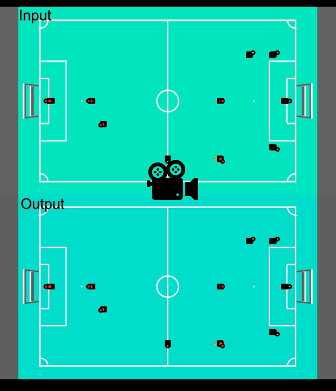
In this stage, 15 image use-cases containing 8 no-violation and 7 violation cases were created and tested. In the below picture, the result of testing the system with one of the free kick use cases is visible. In the left image, the team B have the yellow colour and is at the right half of the field. They are attacking team A with the red colour and have scored a free kick. Two of the team B players are inside the 2m distance from the center of the ball and one of them is the kicker, therefore it is not violating the law. Two of the team A players are inside the 3m distance from the center of the ball. As it is shown, the system has detected 2 violators for team A and one violator for team B, correctly.

Why we had to do this?
To verify that the system works under different circumstances and situations, we had to make this step before testing the system with the defined frequency and frames. In other words, one step before testing the system with a video, is to make sure that it is capable of detecting violations and implementing basic laws in these violations. Therefore, we made these images to simulate the frames from a video. Furthermore, these use-cases were considered for testing specifically the functional requirements.
How the image use-cases were created and tested?
There were no data available from the camera located at the top of the tech-United’s field. Therefore, the use-cases had to be created artificially. In the first step, for each of the cases (free kick, kick off, etc.) violation cases and no-violation cases were considered. One extra use-case for kick off is when team B has the free kick in their own half of the field near the penalty area and as a result, one of them is allowed to be closer to the ball. In the next step, using the MATLAB Simulink, players were located at the specified locations and images were created. Finally, each of the use-cases was tested with the algorithm to make sure that it works for every possible situation.
The 15 cases are explained below.
- First case is when the team B in yellow colour are attacking team A in red colour and they gain a corner kick. This case has been designed in such a way that none of the players are violating the required distance.
- Second case is for a corner kick as well, however in this case, one of the team B players and one of the team A players are violating the law just before the kick happens.
- The third case is a dropped ball. One of the team B players is inside the penalty area, thus is allowed to be in a less distance from the ball than 1m. therefore, this case is a no-violation one.
- The fourth case is another dropped ball case in which one of the team A players gets close to the ball and violates the 1m rule. This case is a violated one.
- The fifth case is a free kick. Every player is in the allowed distances from the ball and as a result no violation happens in this case.
- The sixth case is a free kick in which the ball is placed near the penalty area of team A’s half of the field. As it is shown in the image, two of the team A players are in the penalty area, which is not acceptable based on the requirements and the law book. Therefore, it is a violation case.
- The seventh case is a free kick in which one of the team A players is inside the 3m radius distance from the ball and one of the team B players is closer to the ball than 2m. therefore, it is a violated case.
- The eights case is similar to the 6th case, but in this case one of the team B players is inside the team A’s penalty area and it is closer to the ball than 2m. therefore this is a violation case.
- The nineth case is when team B has the free kick in their own half of the field near the penalty area. Therefore, one of the team B players is allowed to be anywhere in the penalty area, even closer to the ball than 2m. this is a non-violation case.
- The tenth case is a goal kick where the goal keeper of team B is going to start the game. None of the players is inside the violation area and this is a no-violation case.
- The eleventh case is when players get close to the goalkeeper. In this case, one of the team B players and one of the team A players are violating the law. However, in this case, because of the distortion in the image and the colour being not visible enough, the result was not correct and showed 2 violators for team B. nonetheless, this is a violation case.
- The twelfth case is a kick-off, where one of the team B players has to start the game and none of the robots is inside the violated circles around the ball. This is a no-violated case.
- The thirteenth case is a kick-off and one of the team A players is inside the 3m radius circle around the center of the ball and one of the team B players is inside the 2m radius around the ball. Therefore, these two players are violating the law and this is a violation case.
- The fourteenth case is a throw-in case for team A. none of the players is violating the distance law and this is a no-violation case.
- The fifteenth case is a throw-in and one of the team A players is inside the 2m radius circle around the center of the ball and one of the team B players is inside the 3m radius circle from the ball. This is a violation case.


Video use case testing
What has been done in video use-case testing?
Two video use-cases were created for testing the performance requirements.
The first scenario is when a player cuts straight into the area that is not allowed for it to enter based on the zone violation rules, with its maximum speed. The second scenario is being created with assuming a case when one player goes toward the ball and returns, with its maximum acceleration.
Why we had to do this?
The system has to be verified if it is capable of capturing every frame from a video. The two scenarios were made based on the extreme cases to make sure that the system is able to cover the worst scenarios. Even though 'tic toc' has been used to test the speed of the algorithm and by checking with the requirements, the performance of the system could be verified from a quantification perspective. Nevertheless, it is still a more intuitive way to see the influence of 'speed' in the real detection cases.
How the video cases were created and tested?
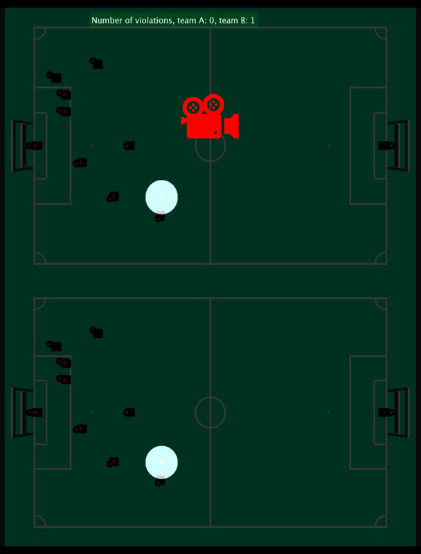
In MATLAB Simulink, one use-case has been created in such a way that there is a dropped ball event. One of the players moves with its maximum velocity on a straight line. During this movement, the player is in tangent with the 1m area of interest around the ball and consequently, will cut this area for a short amount of time. It is expected from the system to detect this violation.
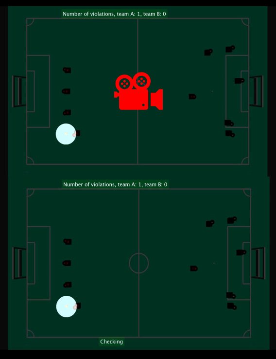
The second use-case is the dropped-ball event, as well. One player moves toward the center of the area of interest and enters this area for about 2cm and accelerates for going back out of the area again. It is expected from the system to detect this 2cm violation during the short amount of time of this movement.
Two detection schemes are used for testing, including 'with time constraint situation' and 'without time constraint situation'. Time constraint means that there is no delay allowed and the detection should be always in real time. Since the camera has over 30 FPS, the algorithm might be slower and has to jump between frames and select them for detection, thus some frames containing violation information may be missed. No time constraint means that the algorithm detect all frames which may lead to serious delay. In the video showing the 'without time constraint situation' below, the testing video was simulated slowly in the first phase and has been accelerated afterwards.
What can we conclude from the results
There are two videos below showing the results of the test. First video shows the Scenario 1 while another shows the Scenario 2. In both videos, the upper video is the situation without testing time constraint and the lower one is with time constraint.
By viewing the preview of each video (or view the entire video by click on the preview), it is obvious that under time constraint, there might be chances that the system missed the frames containing the violation information, since the speed of the algorithm is around 500 ms, only 2 out of 30 frames are processed per second. In scenario 1, the system does not catch the violation frame while the violation is caught in scenario 2 due to luck.
The reason why the system is slow is because we implemented and tested the algorithm in Matlab, it is much slower than real world implementation by C or C++ on hardware. We can predict that the performance of the system should be much better if implementation can be done in real hardware using fundamental computer languages.
Long video simulation
The following video shows use-case of the designed system algorithm. The game state transition “Free kick” happens due to collision between two players (detection of which is out of the scope of this project) at 10 seconds. The algorithm starts working at this point observing ball-player distance violation. When all the players of the attacking team, except one kicking the ball, are outside the 2-meter radius circle around the ball, and opposite team players are outside the 3-meter radius circle, the algorithm allows the ball to be in play. The ball comes in play after 30 seconds of the video pass.
Conclusion and recommendations for future work
In this section, the conclusions from different aspects are listed.
Conclusion
- The concept of using a static camera placed at the top of the field for refereeing the games was explored using simulation.
- Ball-player distance violation check algorithm task for kick-off, free kick, corner kick, throw-in, goal kick, penalty kick, and dropped-ball has been considered.
- Fifteen scenarios based on the distance violation in kick-off, free kick, corner kick, throw-in, goal kick, and dropped-ball have been created.
- Two extreme cases for testing the required frequency of the system have been considered and two video use cases have been made based on them.
- Image and video use cases have been created using MATLAB-Simulink.
- Individual software blocks for zone detection, ball detection, player detection, player team identification, area of interest, and decision making were built separately and integrated into the final step together.
- The integrated system was tested with image and video use cases and the results have shown that the system prototype is operable, however not all technical requirements have been met.
- The algorithm was tested in a software simulation environment and hardware implementation can be done in the future.
Recommendations
Vision system:
As was previously mentioned, the simulated vision system experiences serious limitations: perspective distortion and object occlusion, which can lead to the whole system malfunctions in real-life scenarios. In order to overcome these limitations, the next design solutions are recommended:
- Moving camera. Mounting a camera on a moving agent (a runner slide or a drone) will allow positioning a camera right above the area of interest which, in turn, will minimize the influence of perspective distortion on ball-player distance violation check.
- Multiple cameras. This arrangement may be used to make a panoramic view of the field as part of image pre-processing. This will provide information about the game situation around the whole field and will allow tracking separate players that are close to each other. Possible concepts are described in the table below.
| Concept | Pros | Cons |
|---|---|---|
| Four cameras at the field corners |
|
Image distortion (more pre-processing steps, i.e., depth estimation, plane transformations) |
| Top camera + 2-4 cameras on the sides of the field |
|
Mounting top camera may not be feasible above every soccer field |
Task implementation:
- Identify each player in the field. This will allow predicting violation by estimating trajectories of specific players.
- Collision detection. This task was also mentioned as a hard-to-implement by human-being referees. The reason for it is that human-beings cannot precisely measure players velocity and are not able to observe every part of the field simultaneously. Additionally, skills developed in scope of this project for ball-player distance violation check, are similar to skills needed for collision detection.