Group Members
| Name: |
Student id: |
| Mian Wei |
1035075 |
| Zhihao Wu |
1041226 |
| Petrus Teguh Handoko |
1033085 |
| Bo Deng |
1034694 |
| Bo Cong |
0976759 |
| Jian Wen Kok |
0808353 |
| Nico Huebel |
Tutor |
Initial Design
| The initial design for the maze challenge is elaborated below. It includes the requirements, functions, components, schematic of program structure, specifications and interfaces to define the working of PICO. The file for the initial design is included here:
File:Assignment-for-week1.pdf
|
Requirements
PICO should:
➢ Drive autonomously through maze
➢ Take a turn without touching walls
➢ Detect turns or branching corridors
➢ Avoid collisions with obstacles (including walls)
➢ Drive straight and rotate smoothly
➢ Not stand still for more than 30 seconds
➢ Avoid getting trapped in the maze
➢ Recognize the door
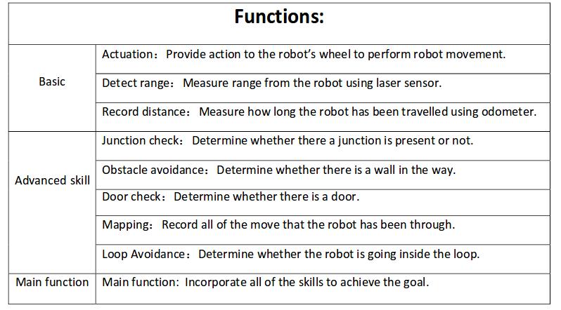
Functions
Below is the scheme of PICO's functions. The basic skills enable the advanced skills, and all these skills are integrated into the main function to finish the maze challenge.
Components
Drive control
‐Holonomic base (omni‐wheels)
‐Pan‐tilt unit for head
Detection
‐170◦ wide‐angle camer (Unavailable in this project)
‐Asus Xtion Depth sensor (Unavailable in this project)
‐Laser Range Finder (LRF)
‐Wheel encoders (odometry)
World model
Computer
‐Intel I7
‐Ubuntu 14.04
Specifications
|
- Maximum translational speed of 0.5 m/s
‐ Maximum rotational speed of 1.2 rad/s
‐ Door template: width of 0.5 ‐ 1.5m, depth of 0.3m, seen in figure below
‐ LRF accuracy and range unknown
‐ Odometer accuracy unknown
|
|
|
|
Interfaces
The odometer and LRF provide data for mapping the environment.
The algorithm sets nodes on the junction as a setpoint for the navigation and calculates the route.
The results of the calculation are interpreted as movement orders, which control the actuators.
The odometer and LRFare used to constantly track the environment changes.
The recorded changes are compared with the reference and the recognition program can then distinguish obstructions, dead ends, doors and junctions.
Corridor Challenge
Design
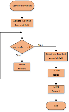 Flow chart of corridor movement For corridor challenge, PICO is designed to behave as follows:
- First, PICO moves forward with a modified potential field.
- When PICO detects a junction, the potential field is switched off and the program directs PICO to stop in the middle of the junction.
- PICO rotates 90 degrees and moves forward, finishing the challenge.
These control sequences are illustrated in the flow chart on the right side.
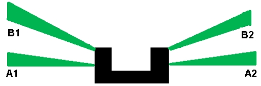
Modified potential field
Laser beams A1 and A2 are used to check the relative distance between the left and right sides of PICO. Based on this measurement, the robot will be adjusted to the middle of the corridor by movement of both translation and rotation velocities.
Code: Potential Field
Junction detection
Laser beam B1 and B2 are used to identify whether a junction exists or not. When a junction is detected, the potential field is switched off. PICO continues the forward movement until either A1 or A2 detects the junction. This sequential control guarantees that PICO makes the turn at the correct position. Then PICO turns 90 degrees and moves forward to finish the challenge.
Code: Junction detection
Result
PICO was unable to complete the corridor challenge:
- In the first trial, PICO moved straight forward without a potential field function. When PICO detects the junction, it stopped and rotated 90 degrees in the opposite direction. This inevitably resulted in crashing into the walls.
- In the second trial, PICO did not detect the junction and drove straight forward. This time, PICO has installed the latest program.
|
Evaluation
In the first trial, we used our old program that has proven to be successful as seen in the video. Unfortunately we did not push the correct version to PICO.
In the second trial, we used our latest program. The potential field function is added since there is a chance that PICO would run into the walls without it. The new program works in the simulation but it has not been tested in the real settings. We had problems of controlling the odometer to turn PICO correctly. During the challenge, this program was run anyway, since the backup program was failed in the first trial. Without being tested in experimental runs, our program unluckily failed us again. Later on, a mistake was found in the junction detection section.
After all, we think the potential field function should be properly added to PICO, to prevent colliding into walls; instead of a static turn that is implemented currently, a smooth turn movement is suggested to cut the time expense.
|
|
 Corridor challenge simulation |
Maze Challenge
Design
Architecture
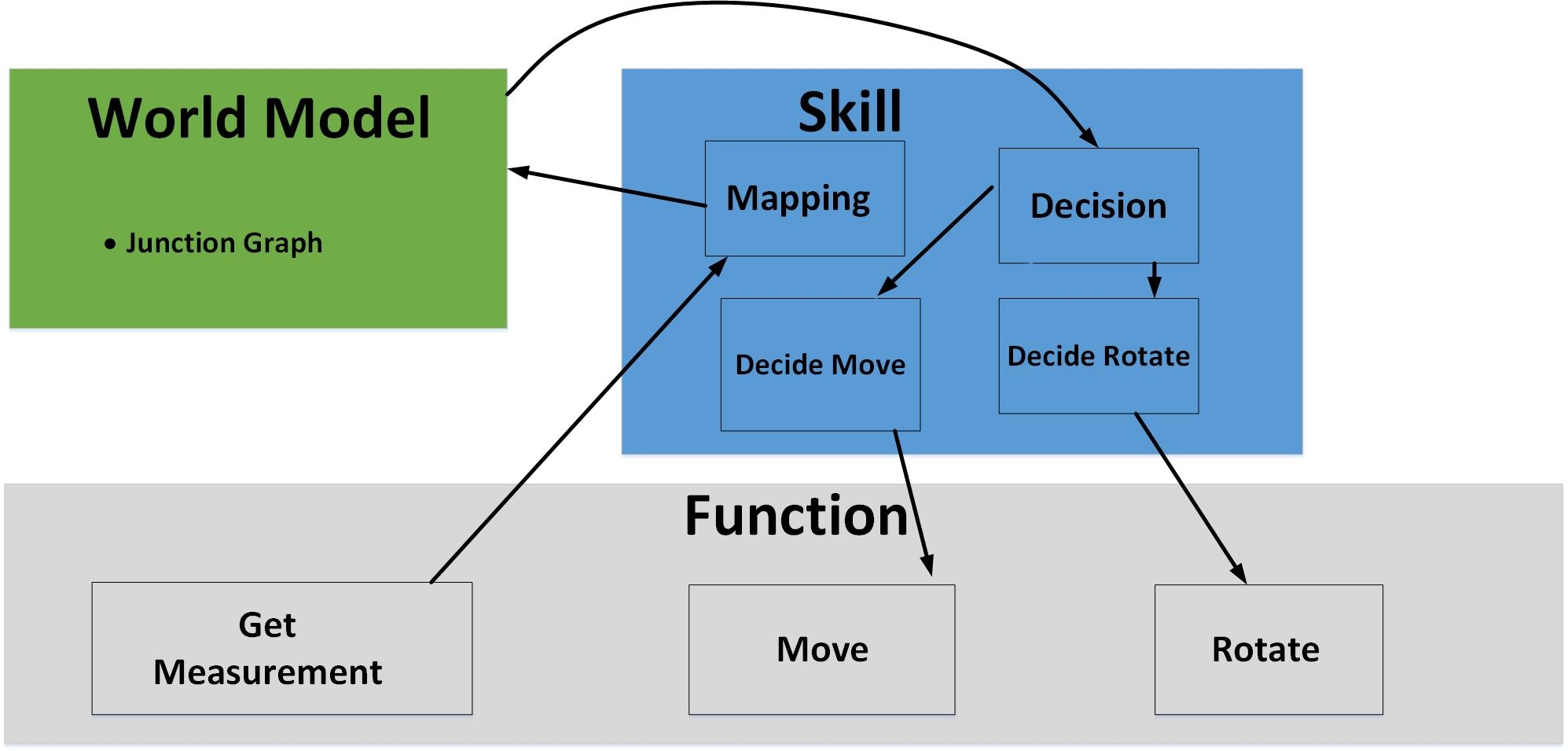
- The architecture diagram on the right is the initial design for the maze challenge.
- The world model block represents the maze environment and the function block represents the necessary functions of PICO to finish the challenge, which includes three subfunctions: get measurements from laser and odometer, translation move and rotate. The skill block represents the brain level program of PICO containing mapping, detection and decision programs.
- PICO detects the environment condition, which would lie into three different scenarios: junctions, open space and doors. After the detection, program proceeds to the decision block, which provides a decision accordingly. Then the decision is conducted by defined function in function block, and PICO will move as the decision requests.
|
|
 Architecture of the program for maze chanllenge |
Main Flow
- The code programmed for maze uses several flags, such as possible_door_flag, junction flag and etc, to decide which part of the program should be executed. Multiple flags will be set according to the situation that the ‘Detection & Decision Block’ has detected, and they will be reset when the corresponding movement is completed. These flags are the basis for the logic of our program. For example, the possible_door_flag is set to be '1' when the ‘Detection & Decision Block’ finds a door, and this flag will be reset when the ‘Door Movement Block’ has been executed completely.
- Seen in 'Structure of main loop', the ‘Initialization block’ will be executed at the beginning as the robot is turned on. After that, the main loop of the program is running in 20 Hz. The main loop consists of four blocks: ‘Detection & Decision Block’, ‘Door Movement Block’, ‘Junction Movement Block’ and ‘Normal Movement Block’. The first block takes charge of junction detection, door detection, open space detection and movement decision.
- First, the robot will detect the existence of the door and returns ‘possible_door_flag’, which indicates the existence and the direction of the door with respect to the robot. When ‘possible_door_flag’ is '1', the running program will skip ‘junction detection’ sub-block and directly execute ‘Door Movement Block’ since the information of junction is not as important as information of door existence. Otherwise, ‘Detection & Decision Block’ will proceed to the next sub-block for junction checking.
- Secondly, the robot will detect the existence of junctions. The junction will be described by ‘junction_flag’ and ‘junction direction flag’. The ‘junction_flag’ indicates the existence of the junction around the robot, and it is set by ‘Junction Detection’ sub-block. The ‘junction direction flag’ indicates the type of junction: left, forward and right. If ‘junction_flag’ is '1' indicating the existence of a junction, the ‘Decision’ sub-block will then decide the direction to which robot should move. If not, the ‘Decision’ sub-block will give the default movement mode, ‘Normal Move Forward’.
- The ‘Open Space Detection’ is inside the ‘Junction Detection’ sub-block which will be introduced later.
- Notice that when the robot is executing actions, the position and orientation of the robot with respect to the maze is changing, therefore, the data collected by laser scanner is not reliable for making another decision. In order to avoid this type of error, we want to block the ‘Detection and Decision Block’ until the last issued command is implemented completely and ‘junction_flag’, ‘possible_door_flag’ are reset. As a result, it is necessary to stipulate that ‘Detection & Decision Block’ can only be executed when both ‘junction_flag’ and ‘possible_door_flag’ are '0'. For example, after a junction or door is detected, another decision will not be made until movement is finished and the other blocks help reset the flags.
- When the execution of the first block completes, “Junction Movement Block”, “Door Movement Block” and “Normal Move Forward Block” will be executed according to the movement command issued by “Detection & Decision Block”. “Normal Move Forward Block” provides forward movement, which is set as default movement. This movement is equipped with potential field protections. This movement will be replaced by “Junction Movement Block” or “Door Movement Block” when decisions are made.
|
|
|
Detection
Junction Detection
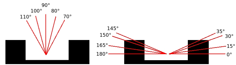
| In the figure 'Laser bundle for junction detection', it shows that three laser bundles in the front, left and right directions are selected for the dectections. To make the performance of detection block more reliable and robust, the detection radius and detection angle are carefully calculated. The detection angle is set to be 48° and the maximum detection range is thereby ±114°.
As a result, the boundaries of three laser bundles are:
- Left bundle: +114° and +66°
- Front bundle: +24° and −24°
- Right bundle: −114° and −66°
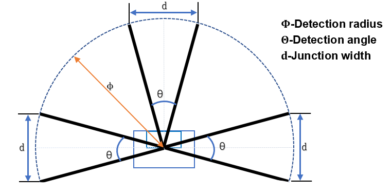 Laser bundle for junction detection To make sure that PICO will not collide with the wall, especially when it is turning at junctions, the width 'd' should be larger than PICO's width. We use the base of isosceles triangle constructed by laser beams of -144° and -66°(for right side, we take 114° and 66°) to evaluate the width of the comming side corridor. The calculation is shown as following.
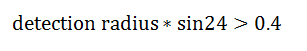
This equation ensures that PICO can only find junction that is wide enough for PICO to move into. The detection radius is therefore set to be 0.85.
A junction is found when both boundaries of one laser bundle have longer detecting distances than the detection radius. All the laser beams inside the laser bundle are measured to increase the robustness of the detection. Only if 80% laser beams have fulfilled the above condition, PICO considers there is a junction.
Two flags are used to describe the existence and feature of junctions: the junction flag and the direction flag.
Junction flag:
- Junction flag is used to describe the exist of junctions
- 0: no junction and only the forward corridor
- 1: existence of left or right junction
Direction flag:
- Direction flag D[3] is an array, and each number represents a direction
- D[0]=true: right junction available
- D[1]=true: forward corridor available
- D[2]=true: left junction available
If junction flag becomes 1, the decision block will be triggered and decide a direction to move PICO.
|
Door Detection
There are two kinds of door, front door and side door.
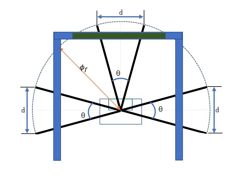
- Front door detection method
Door detection is made by checking the distance of three ranges. The range is defined by angle θ=48°, and detection radius φf.
front door is considered as a subcase of dead end. Hence front door and dead end are detected in the same way. If the average distance in the three detect ranges are smaller than φf, which indicates the discovery of dead end, possible_door_flag=2 will be returned to show the direction of door with respect to the robot
- Side door detection method
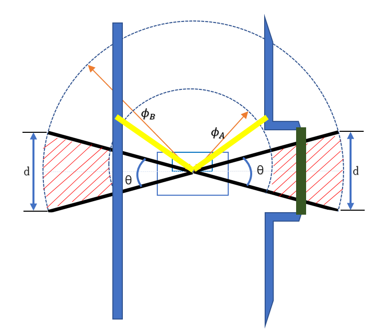
To make detection simpler and reduce workload, “Side Door Detection” block is built as an extension of side corridor detection by using the left and right side detect ranges. As illustrated in Figure "Door Template" in 2.4 Specifications, the depth of door template is around 0.3m and the corridor width is between 0.5m and 1.5m. we use an annulus range with limitation φA=0.7m and φB=1.3m to define the possible door condition (the red shadow in Figure). To avoid the robot trap by the side door detection loop, we consider front data about 45° should smaller than φC=1m (the yellow line in Figure "Door Detection"(right).
For example, considering the right door in the “Door Detetcion”, first check whether the values of two edge laser data.212 and data.2(±24°) are between φA and φB. And then check whether the value of - 45°(laser data.303) and +45°(laser data.696) smaller than a specified constant φC. If the both conditions are satisfied, the percentage of datas whose value is between between φA and φB will be calculated among the data set from -114° to 66°. if 75% data satisfied the length condition (in the red shadow area), which means there is a right side door, possible_door_flag=1 (for the left door possible_door_flag=3 ) will be returned.
possible_door_flag:
- possible_door_flag return the direction of possible door
- possible_door_flag=1: right door
- possible_door_flag=2: forward door
- possible_door_flag=3: left door
|
Door Open Detection
| We use the similar way to detect if the door is opened after waiting for 5 seconds. The forward direction laser bundle is used. If the boundaries and more than 75% laser beams inside the laser bundle detect longer distance than detection radius, PICO will consider door has opened.(Similar as front junction detection)
|
Open Space Detection
"Open Space Detection" block is an extension of "Junction Detection" block. By including another two laser beams ranges around -45°and 45°respectively (red ranges in the figure),the feature of open-space can be distinguished from that of normal junctions. the differences will be introduced below in three different cases in detail:
Openspace flag:
- Openspace flag is used to describe the exist of openspace
- 0: no openspace
- 1: existence of openspace
- Open space appears on the both side of the robot as showed in Figure "openspace-Detection-case1". The feature of this case is likely to confuse the robot with cross junction in Figure "openspave-case1"(right). With laser beam at -45° and 45° added, we can distinguish this case with cross junction because in open space, laser beam at -45° and 45° cannot detect any obstacles within its detecting radius. While if it is cross junction, some obstacle will be detected.
openspace_Detection_case1
- open space only happens on the right side of the robot as showed in Figure "openspace-Detection-case2". The feature of this case is similar to that of right T junction showed in "openspave-case2"(right). In same way, laser beam at -45° helps to distinguish them.
openspace_Detection_case2
- Open space only happens on the left side of the robot as showed in Figure "openspace-Detection-case3". The feature of this case is similar to that of left T junction showed in "openspave-case2"(right). Laser beam at 45° helps to distinguish them.
openspace_Detection_case3
- The code introducing the information of front left/right laser beam into environment detection is positioned at the end of the "junction_detection.cpp", after the detection of junction is completed. The value of junction_flag and int array junction_direction which indicate the direction of the available corridors at the junction has been assigned. Then, checks on the result of LRF at -45° and 45° follows. If there is no obstacle found in one of these two directions, junction_flag will be reset and the information of left junction detection will be cleaned. i.e. the value of junction_direction[2] will be assigned zero. Variable openspace_flag will be set to indicate the discovery of open space, no matter it is left or right one.
And then, it comes to the decision block. Now, the value of junction_flag is zero, Decision block will not execute "Corridor Decision Block" because the condition for this block doesn't hold as showed in figure '"Flow Chart of Decision Block". But the condition for the first case in "Open Space Decision Block" hold in this case and decision in this case is specified as 2(indicator of turning left movement) in this round and another variable "openspace_decision_flag" is set at the end of the this sub-block. When "turning left" movement is completed, same detection procedure is repetitively performed. Because the discovery of right open space, the indicator of the discovery of junctions keep being cleaned and indicator for left junction stays at 0 at the end of "Junction_detection Block", openspace_flag is set at the mean time as stated above. the second time when "Decision Block" is executed, the condition of the first case in "Open Space Decision Block" doesn't hold anymore beacause the value of "openspace_decision_flag" has been set to 1 and no block help to reset it up to now. It is until "Openspce_case3" that "Decision Block" executes sub-block3 and reset the value of "openspace_decision_flag". That is how open-space algorithms works.
The performance of the algorithm is show in video "Open space performance in simulator"
Open space performance in simulator
|
Decision Block
The Decision Block consists of two sub-blocks. One of the sub-blocks is “Corridor Decision Block” and the other block is “Open Space Decision Block”. These two blocks account for decision in corridor and open-space respectively. The switch between two decision sub-block is based on the value of “openspace_flag”, which indicate the existence of the open space.
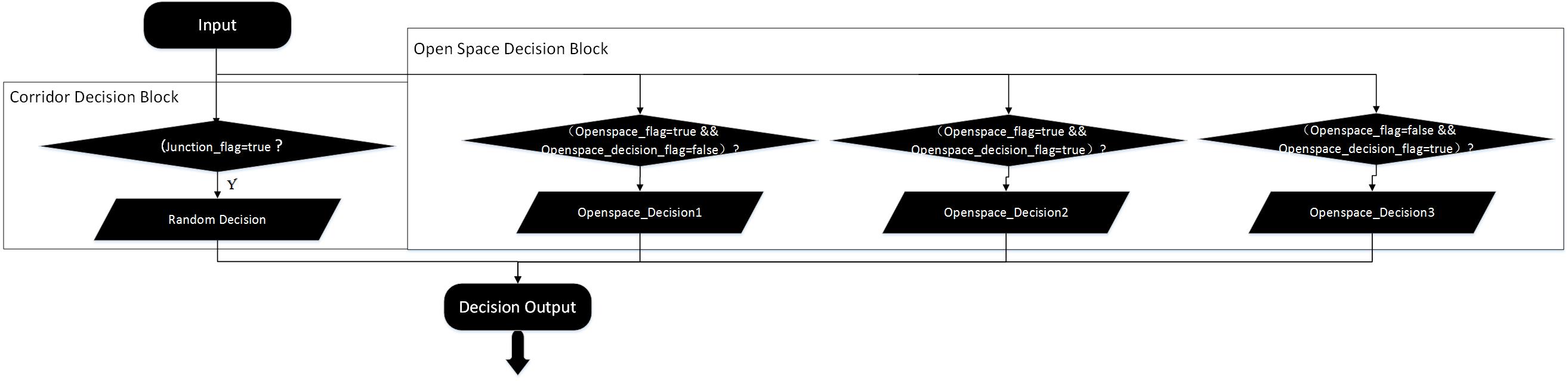
- As demonstrated in “Flow-Chart of Decision block”, when “Decision Block” is executed, program will be navigated to different sub-blocks. Navigating variables are given by “junction_detection” block. According to the internal logic of the “junction_detection” block, “junction_flag” and “openspace_flag” cannot be true at the same time, which ensures that “Decision” block cannot execute “Corridor Decision Block” and “Open Space Decision Block” in same round.
- The detailed decision logic will be interpreted below:
- “Decision Block” is called after “Detection Block”(junction_detection & door_check) has been executed with the information which indicated the existence of door、junction and open space provided. The value of junction_flag ,openspace_falg and openspace_decision_flag are checked.
- Junction Mode:When junction_flag is true, which indicates that junction is found and the absence of open space due to the mutual exclusiveness between junction indicator and open space indicator, Decision Block will be navigated to “Corridor Decision Block”. Arbitrary choice between available corridor directions will be made in “Corridor Decision Block”.
- Open Space Mode:If it is open space detected, “Open Space Decision Block” will be executed, difference priorities are given to different choice. “turning left” is given the highest priority, so the availability of the corridor at left side of the robot will be checked first, and then the check on the availability of corridor at forward direction follows and the last direction to check is right side. With this order, the robot can implement the goal of moving along the left wall in open space. The difference between the second and the third sub-blocks in “Open Space Decision Block” is that they adopt different move-forward mode. When “Openspace_flag==true &&Openspace_decision_flag==true” holds, the robot is moving within the open space or just enter the open space. Under these two circumstance, the moving forward movement controlled in a close loop way to avoid bumping the wall . when “openspace_flag==false && openspace_decision_flag=true?” hold, the robot is gonna to encounter with the exit of the open space. Because of priority detection on open space, the indicator of open space has been reset. To ensure that the robot can move to the middle line of the exit before making the next decision, variable openspace_decision_flag is declared. With this variable distinguishing the last forward movement before leaving the open space with other forward movements in the open space, last forward movement is an open loop controlled one navigating the robot to move forward by 0.5 meters. “Protection Block” is executed all the time, which protects the robot from bumping in open loop procedures.
- As for the first sub-block in "Open Space Decision Block", it will give the movement comment "Turning left" and set variable "openspace_decision_flag" at the end of itself, which ensures that it can only be executed by one time in every open space and only executed at the moment when robot enter the open-space.
 Flow Chart of Decision Block |
| There are three cases that robot may encounter in open space:
|
Case1:
- As figure “openspace_case1” show, the first case that robot encountered in open space. In this case, laser beam at right, left and front side has detected the available corridors at the corresponding directions. While another two laser beams at front right and front left direction for open space detection will reset junction_flag when their detection has proved the existence of the open space. Openspace_flag and openspace_decision_flag will be set at this moment. Movement control will switch to open space mode. According to the priority of different direction choice, the robot will take turning left as first choice and turn to left side.
|
|
Case2:
- Then the robot comes to the second case illustrated in “openspace_case2”. Because the front right laser beam keeps reporting the existence of the open space on right side, open space indicator stay at 1. The priority of direction choice make “Forward movement” be the movement choice. Decision block executes “Open Space Decision Block” and the condition “Openspace_flag==true &&Openspace_decision_flag==true” holds, forward movement is controlled in close loop way.
|
|
Case3:
- The third case following is illustrated in figure “openspace_case3”, laser beam for open space detection are blocked by the wall in front of the robot and thus openspace_flag is reset. While variable openspace_decision_flag stay at 1 and this variable can only be reset by the second sub-block of “Open Space Decision Block”. Now, condition that “openspace_flag==false && openspace_decision_flag=true” holds and second sub-block of “Open Space Decision Block” is executed. With the priority of the choices, forward movement is selected again. However, this time forward movement is controlled by open loop block and the robot will move forward by 0.5 meter if it is not stopped by protection block.
|
|
Movement
Door Movement
| After the door check function has been completed, the door movement function is then called. The possible door flag obtained from the door check function is then utilized to determine the position of the door:
If the possible door flag is 1 the robot has to turn to the right, if the flag is 2 the robot has to move straight and if the flag is 3, the robot has to turn left. After making the turn and adjust its position with respect to the potential door, the “io.sendOpendoorRequest” command which represented as a bell rings is executed and the robot has to wait 5 seconds for the door to open. After 5 seconds has expired, the robot then scan whether the door has opened or not.
If the door is opened, then all the flag in the function are cleared and then the program will jump out from this door movement function into turn straight in the junction movement function. If the door is not opened (which means false door is detected) then the robot needs to make a turn. The turn that the robot has to made is based on where the door was before. If the door was detected in front then 180 degrees rotation is executed, if door was in the left then 90 degrees rotation to the right is executed and if detect the door was in the right then 90 degrees rotation to the left is executed. After the rotation is done, then all of the flag related to the door check and movement are cleared and the program back to the main function.
There are few additional flags being used in this door movement function. Calibration flag is used indicate that the robot has adjusted its position with respect to the potential door. The rotate finished flag is used to make sure the robot has finished the rotation. The signal sent flag indicates whether the open door request has been sent or not. The waiting finished flag is used to indicates that the waiting time for door to be opened has been expired.
code snippet: door_movement.cpp
|
|
Junction Movement
The Junction Movement function consist of five cases: turnStraight, TurnRight, TurnLeft, protection and movForward.
turnStraight:
PICO shortly moves straight for 0.5m or when counters time[3s] has passed and continues with the moveForward function. The counter is needed to prevent the program go into a loop when PICO is not able to move the distance. The forward movement is protected by 5 laser sectors. When it is too close to the wall or obstruction, the forward movement will move backwards with an speed of -0.2m/s. When the laser beams for the obstruction detection on the sides of PICO detects that it is too close to the wall, the program goes into the state of protection and moves PICO away from the obstruction.
turnRight and turnLeft:
Both cases turnRight and turnLeft rotates 90 degrees to the corresponding direction and measures the rotation with the odometer to determine when to stop. To make sure that the odometer is accurate enough, the rotating speed is set at 0.2 rad/s.
moveForward:
After finishing the turnStraight, the code will go into the movForward state. PICO moves straight for 5m or stops when counters time[5s] has passed. This movement is exactly the same as the turnStraight movement except for the distance and countertime.
protection:
When an obstruction is detected in the turnStraight or movForward, PICO then stops and moves sideways to avoid the obstruction.
The protection in the junction_movement.cpp and move_forward.cpp are explained here: protection
The code snippet is included below:
code snippet: junction_movement.cpp
|
Move Forward
| Similarly to the junction_movement.cpp, move_forward.cpp uses three front laser bundles to adjust the speed. The forward speed is either 0.5m/s when the detection allows or -0.2 m/s otherwise. What differs from the junction_movement.cpp is that the forward movement will not stop when it adjusts with the side movement to avoid obstruction. With 6 laser bundles, 3 at both sides, it adjusts the sidewards speed. When it detects a obstruction, it will move sidewards to avoid the obstruction.
code snippet: move_forward.cpp
|
Protection
The picture on the left is the front detection for adjusting the forward velocity and on the right picture is the side detection to adjust the sideways velocity. All laser beams takes the average of 15 points. The forward speed is either 0.5m/s when there is no obstruction in the front or -0.2 m/s otherwise. The sidewards speed is 0.2m/s when an obstruction is detected or 0 m/s otherwise. Below is the protection in action to avoid collision.
The code snippet for side protection here:side protection
The code snippet for forward protection here:forward protection
|
Result
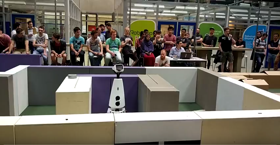
Unfortunately, our algorithm failed again in the challenge because some configurations don't well fit the dimension of the maze. The performance of our robot is disappointing as the follow video "Maze Challenge Record" shows:
|
|
|
Maze challenge record
|
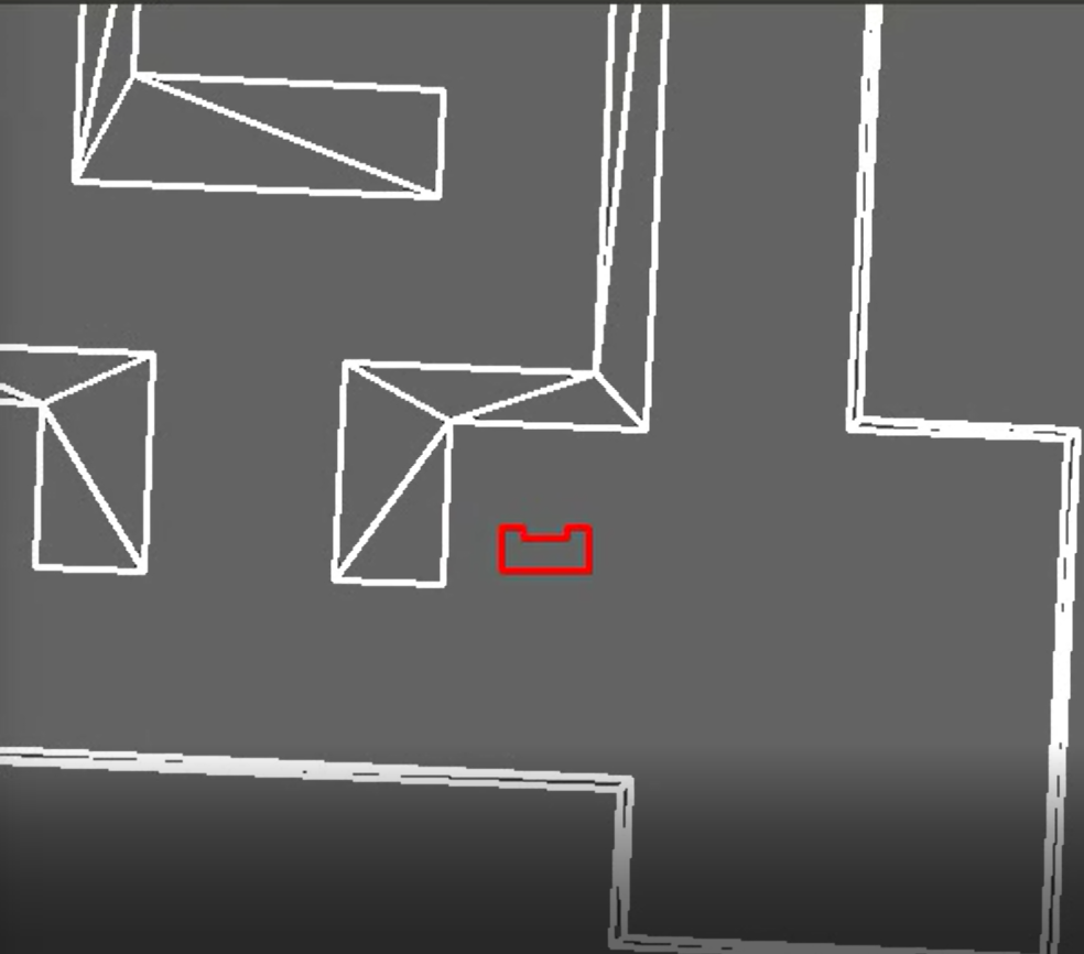
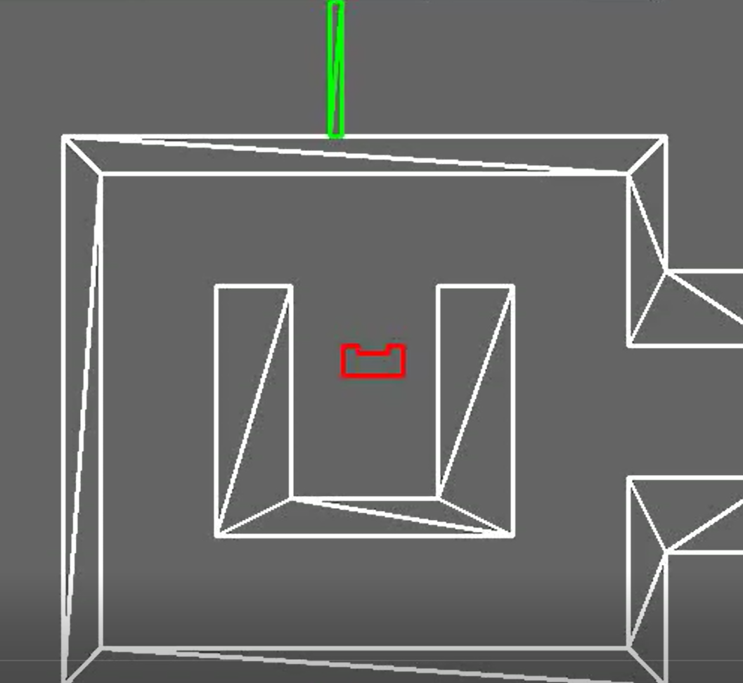
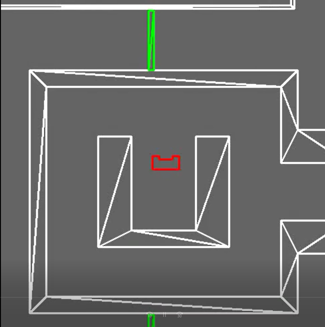
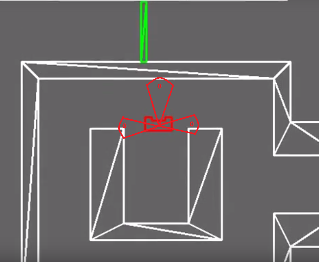
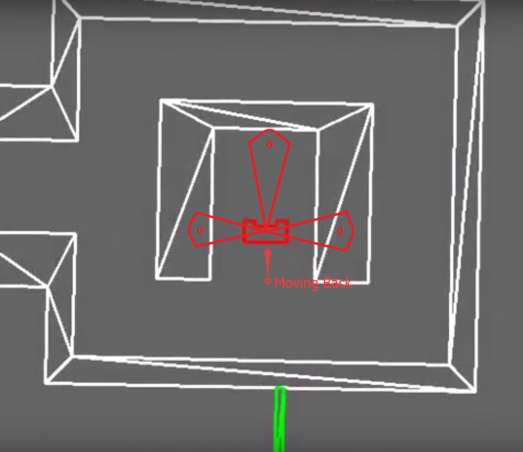
The robot got trapped at the very beginning. The reason is that the distance which indicates ‘Forward Dead End’ was too large and it made robot conclude that there is no way forward before it moved out of the U shaped structure. At this moment, the robot find the distance in left, forward and right direction are smaller than the designed threshold, which made the robot conclude that it was located in a dead end and door checking algorithm at dead end was activated. After ‘door open signal’ was sent, the robot waited for 5 seconds and find there doesn’t have a door. According to ‘Door Movement Algorithm for Dead end’, If no door was detected open, the robot would rotate back by 180° after waiting for 5s. This time the robot meet a dead end again. So the same movement repeated again. And it would rotate back after a failed try to open the door at the second dead end. In this way, PICO got trapped in the loop and would never find way out.
Phenomenon stated above is illustrated more clearly in Figure ‘First Dead End’ and ‘Second dead end’.
|
|
| First dead end & Second dead end
|
| Causal analysis on the failure of the Maze Challenge was proved by simulator as well. We make the configures same as what we applied in Experiment and executed the code on simulator, same phenomenon was observed as video "Dead end loop in simulator" shows.
|
|
| Dead end loop in simulator
|
| After the maze challenge, we lowered the value of detection radius for front obstacle detection and ran the code in simulator. Because it is arbitrary decision, the time PICO costed for maze solving is not a constant. But we found the maze could always be solved within 5 mins. Video "Maze solving performance in simulator" shows that "Maze is solved successfully within 5 mins"
|
|
| Maze solving performance in simulator
|
Evaluation for Maze
- The problem of complexity:
By adding states we increase the complexity of the system and this can result very easily into undesired behavior as it is observed. PICO can only perform 20 tasks each second and since we are moving at a speed of 0.5 m/s and this combined with the many states the program has, can result into more undesired behavior.
Right now, states are being used to prevent undesired behavior. This way of solving requires the making of repeating states with different conditions which in itself increases the complexity.
It is proposed to cut down the number of states and only focus on the key tasks: moving block, detection block, door handling block, maze solving block. A supervisory controller is implemented manually and undesired behavior is filtered based on observations in simulations and testing in the real environment. By implementing techniques for the synthesis of a supervisory control would have reduced many undesired behavior beforehand.
- Oversensitiveness of quantitative algorithm:
Mathematical principle of the the algorithm is quantitative. For example, the condition for the discovery of front door detection is that the distance of three directions of PICO (right,left and front) are smaller than specified values. And it was the improperly selected threshold of the front side make PICO go into loop in the maze challenge. By reducing the detection range of a door, this problem was solved. i.e., the portability of quantitative algorithm is oversensitive to the dimensions of the environment, which may lead to mis-detecting and mis-operating. Besides, the rotation of PICO at the junction is controlled in open loop way, and the angle of rotation in junction turning part is integer multiple of 90° based on the precondition that all f the angle of junction is 90°. what if the angle of junction is not 90°? this algorithm cannot deal with a more general problem because of its quantitative based principle. Quantitativeness of the algorithm lower the portability of the it and make PICO oversensitive.
- Performance balance with properly selected config is needed
To solve the problem of oversensitiveness, we add protection block to prevent collision and improve robustness. Longer activation distance improve the performance of Protection with larger buffer distance, while it led to another problem-protection deadlock in narrow corridor.The protection field was wider than the corridor. Because when an obstruction at the side was detected, protection causes the forward velocity to be zero and activates the sidewards velocity. This resulted in a deadlock. By reducing the protection field, this problem could be solved. The balance between good protection performance and avoidance of protection deadlock is needed.
Our former design of strategy was using a combination of mapping and depth first search. The problem was that junction detection did not work well, it sets flags where it should not. Thus, this strategy was rejected and we used random decisions. To solve the issue of junction detection,the split and merge algorithm can be used to detect the corners and walls. Another solving strategy that proved to be functioning well is the pledge algorithm that group 10 used.
- Too much "innovation" and too less reference:
During the project, we tried to design our own methods to solve the maze instead of using the methods which have been provided in previous WIKI. For example, we designed a new way to solve open space, instead of using 'virtual wall'. Design new method considerably increases the complexity but the result seems not good. In order to avoid this problem, it will be wise to just use the method provided in WIKI. If we still have time, then we can try to create our own method.
- The logic of whole system is built on the base of flags. The flags mainly have three functions:
- Indicate the features around the Robot:
- junction_flag: indicate the discovery of junctions around the PICO
- Possible_door_flag: indicate the discovery of possible door
- open_space_flag: indicate the discovery of open space around the PICO
- …
- Flags shown above performance as an indicator of feature discovery.
- Indicate the completion of Movement
- junction_flag: when junction movement is completed, junction_flag will be reset.
- possible_door_flag: when door movement is completed, ‘’possible_door_flag’’ will be reset
- …
- Flags shown above indicate that the corresponding movement is completed.
- Indicate the previous state of the robot by corporation with other flags
- openspace_decision_flag: with the cooperation with ‘’openspace_flag’’, it indicate the current state and previous state of the PICO.
| scope="col" |
openspace_flag==1 openspace_decision_flag==0
|
previous state is in corridor, current state is in open space (corresponding movement is turning to left if there is space to move to on the left side )
|
| scope="col" |
openspace_flag==1 openspace_decision_flag==1
|
previous state is in open space, current state is in open space as well (corresponding movement is moving forward)
|
| scope="col" |
openspace_flag==0 openspace_decision_flag==1
|
previous state is in open space, current state is "about to encounter with the next corridor"
|
- With these flags indicating the state of the PICO, the logicalness of the system is guaranteed.
- The key issue of this structure is the position where the flags should be set or reset, it is also where we spent much time.
- Innovation of detection method:
- The method to solve open space problem, junction detection and door detection are purely by innovation,.
|
Evaluation group9 EMC 2017
|
We were able to make two programs that were able to solve both challenges in simulation. The corridor challenge was failed because of a mistake in pushing the program and inefficient use of the tests in the real setting due to lack of know how it update in git. From the maze challenge we learned that robustness is critical. The protection and detection works but is too restricting causing PICO to fail the challenge. Below we listed some more conclusions and experience we acquired for this course.
- learned programming in c++
- learned to work with GIT
- reuse code instead of repeating the code
- first robustness then performance
- have a clear understanding of the design among team members is critical
- clear and frequent communication and clarity in assigned tasks will improve progress of the group
- design, make the code, test and debug a lot and redesign if the design is not proper
|
Code snippets
corridor challenge
potential field
junction detection
maze challenge
Door Movement
code snippet: door_movement.cpp
Movement
code snippet: move_forward.cpp
code snippet: junction_movement.cpp
Files
File:Assignment-for-week1.pdf