System Architecture Robotic Drone Referee: Difference between revisions
(Created page with '<p> Any ambitious long-term project starts with a vision of what the end product should do. For the robotic drone referee this has taken the form of the System Architecture prese…') |
|||
| Line 23: | Line 23: | ||
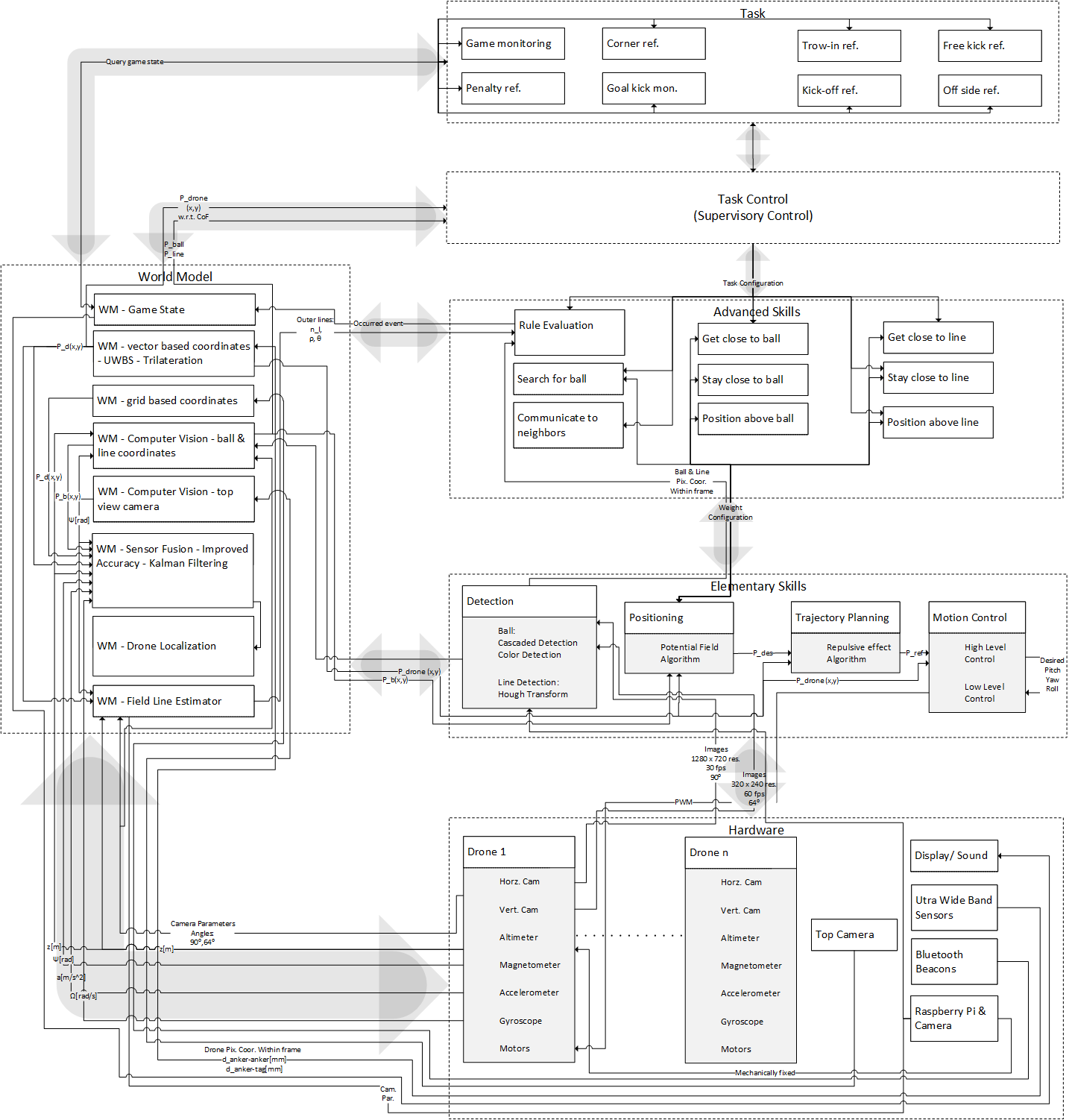
There are six main blocks: The system architecture consists of six main layers (see Figure 1 below): A world model, a hardware layer, elementary skills, advanced skills, task control and a task layer. These are all interconnected bilaterally. Communication is in the form of either, data flow, synchronization, discrete events or configurations etc. The working principles of, and relations between the layers are explained through example use cases. | There are six main blocks: The system architecture consists of six main layers (see Figure 1 below): A world model, a hardware layer, elementary skills, advanced skills, task control and a task layer. These are all interconnected bilaterally. Communication is in the form of either, data flow, synchronization, discrete events or configurations etc. The working principles of, and relations between the layers are explained through example use cases. | ||
[[File:SystArch roboticdronereferee.png| | [[File:SystArch roboticdronereferee.png|1000px|thumb|center|Figure 1: Proposed System Architecture]] | ||
* Hardware: | * Hardware: | ||
Revision as of 09:53, 1 April 2016
Any ambitious long-term project starts with a vision of what the end product should do. For the robotic drone referee this has taken the form of the System Architecture presented in this section. The goal is to provide a possible road map and create a framework to start development, such as the proof of concept described later on in this document. Firstly the four key drives behind the architecture are discussed and explained. In the second part a detailed description and overview of the proposed system is given.
System Architecture - Design Choices
- Key drive I: Optimally utilize limited communication resource:
- Choose Central Task Control solution: Configure only what is necessary for a specific task, i.e. share tasks (advanced skills) and share resources (communication) as much as possible.
- Key drive II: Develop a flexible system:
- Choose System of cooperative agents: Choose a multiple drone agents solution amongst which tasks/skills and resources (communication) are shared.
- Key drive III: Develop a scalable system:
- Choose multiple drone solution (adding more drone-agents is easily feasible)
- Choose Ultra-Wide Band System for drone localization (adding more drone-tags is easily feasible).
- Key drive IV: Develop an system with adaptable accuracy:
- Choose multiple sensor/ drone agent solution: The systems becomes fault tolerant due to redundancy of agents.
- Choose Ultra-Wide Band System (UWBS): The system is accurate especially in static cases and becomes more accurate when the number of UWBS tags is increased.
- Choose Computer Vision, especially for ball/line detection.
Detailed System Architecture
There are six main blocks: The system architecture consists of six main layers (see Figure 1 below): A world model, a hardware layer, elementary skills, advanced skills, task control and a task layer. These are all interconnected bilaterally. Communication is in the form of either, data flow, synchronization, discrete events or configurations etc. The working principles of, and relations between the layers are explained through example use cases.
- Hardware:
- Drones: The referee system is chosen to be a system of cooperating systems, i.e. a multiple drone solution is selected. Instead of one drone, multiple drones are used together for refereeing purposes. In this sense, a drone is considered a smart sensor. With a camera on board it is a smart 6 DOF mobile camera. On request it is able to perceive a part of the world within its vision.
- Ultra-Wide Band System: Next to the drones, auxiliary sensing equipment are used. E.g. an Ultra-Wide Band System is used to measure drone position in an external coordinate frame.
- Top camera: External cameras can be used as well. E.g. a top camera can be used to measure drone orientation from a top view.
