Mobile Robot Control 2023 Group 9: Difference between revisions
m (→Real Robot:) |
mNo edit summary |
||
| Line 41: | Line 41: | ||
===Real Robot:=== | ===Real Robot:=== | ||
Result: https://photos.app.goo.gl/8w9H96boxiLcTq5cA | Result: https://photos.app.goo.gl/8w9H96boxiLcTq5cA | ||
<br /> | |||
==Assignment 3: Localization 1:== | |||
'''Part 1:''' The odometry data was successfully read by the script that was created. The current values for the x,y, and a data is printed, and the difference between the previous readings and the current readings are also displayed. | |||
'''Part 2:''' | |||
'''Part 3:''' | |||
Revision as of 23:39, 22 May 2023
Group 9:
| Name | student ID |
|---|---|
| Ismail Elmasry | 1430807 |
| Carolina Vissers | 1415557 |
| John Assad | 1415654 |
Exercise 1:
dont_crash design: The idea was to move forward until an object is reached (0.5m within +/-45 deg) and then stop. If this object is removed, the robot should continue moving forward until it reaches another.
- Noise: it is there, and is slightly jittery. All objects at the height of the laser scanner are seen if they are not too far away (resulting in an inf range). If you walk near the robot, the legs look like lines that are oriented perpendicular to the robot.
- done
- yes, it works the same as in the simulation as long as the speed is low enough and the distance is high enough. ie, the robot cannot move extremely fast (ie 0.7m/s) or stop too close to an object (ie 0.3m) with the real robot.
- https://photos.app.goo.gl/qFkDADTsP4tE5w4A8 (see video here)
Assignment 1:
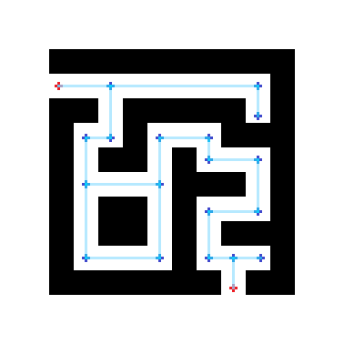
The nodes can be placed more efficiently by only placing nodes at places where there is a choice in directions. Numerous nodes placed one after another in a straight line require computation, but do not offer any added value to the system, since the only choice is to continue forward. In the Figure, red nodes are the start and end nodes, while dark blue nodes are the internal nodes. The light blue lines are all possible connections to follow.
Assignment 2:
We implemented an open space approach. This approach seemed best to us, as the majority of the other approaches required setting a goal, which seemed counter-intuitive due to the uncertain odometry of the robot. Using a look-ahead distance, and a looking angle, we searched for the longest range of angles that the robot could see uninterrupted further than or equal to the look ahead distance. Then we rotated the robot to move in that direction.
Simulations:
Easy map: https://photos.app.goo.gl/CprLeQJM3VMo75UE6
Harder map: https://photos.app.goo.gl/hmdwc545hH43QAhB9
Real Robot:
Result: https://photos.app.goo.gl/8w9H96boxiLcTq5cA
Assignment 3: Localization 1:
Part 1: The odometry data was successfully read by the script that was created. The current values for the x,y, and a data is printed, and the difference between the previous readings and the current readings are also displayed.
Part 2:
Part 3:
