Mobile Robot Control 2023 Group 11: Difference between revisions
| Line 38: | Line 38: | ||
====Assignment-3==== | ====Assignment-3==== | ||
The physical robot was moved and the odometry data was recorded in eah position of the robot. The distance moved by the robot was measired physically using a measuring tape and compared with the odometry data. The table below shows the data | |||
{| class="wikitable" | |||
|+ | |||
!Experiment | |||
!Measured using | |||
!Distance moved in 'x' direction | |||
!Distance moved in 'y' direction | |||
!'θ' angle rotated | |||
|- | |||
|1 | |||
|Measuring Tape | |||
| | |||
| | |||
| | |||
|- | |||
| | |||
|Odometry | |||
| | |||
| | |||
| | |||
|- | |||
|2 | |||
|Measuring Tape | |||
| | |||
| | |||
| | |||
|- | |||
| | |||
|Odometry | |||
| | |||
| | |||
| | |||
|- | |||
|3 | |||
|Measuring Tape | |||
| | |||
| | |||
| | |||
|- | |||
| | |||
|Odometry | |||
| | |||
| | |||
| | |||
|- | |||
|4 | |||
|Measuring Tape | |||
| | |||
| | |||
| | |||
|- | |||
| | |||
|Odometry | |||
| | |||
| | |||
| | |||
|} | |||
The physical robot will have wheelslip which will be recorded by the odometer. The measurement by odometer can be slightly noisy because of physical sensor limitations. | |||
From the experiment it is observed that the odometer does give pretty accurate measurements and can be used to detect the position of the robot. | |||
===Assignment 4 -Localization=== | ===Assignment 4 -Localization=== | ||
Revision as of 12:32, 2 June 2023
Group members:
| Name | student ID |
|---|---|
| Anagha Nadig | 1830961 |
| Sarthak Shirke | 1658581 |
| Idan Grady | 1912976 |
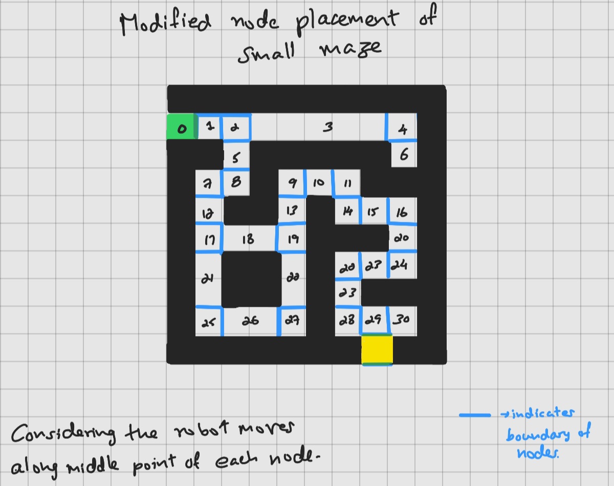
A* algorithm is more effiient when there are fewer nodes to consider on the map and is faster. In the current map, there are multiple nodes which are adjacent in continuum with each other. This means that the robot can travel long distances without any obstruction. These nodes can be grouped together to form a single node.
The figure below shows the modified node placement of the small maze which can increase the efficiency of the A* algorithm.
The local path planning algorithm open space method is implemented, to avoid the obstacles detected by the robot while moving. The Laser data obtained when the robot scans the area is used to detect obstacles and determine their position with respect to the robot's frame of reference. The robot is stopped if there is an obstace within a minimum distance from the robot. The area of the open space between the detected obstacles within the field of view of robot is calculated. The heading of the midpoint of the largest open area is obtained and the robot is given a command to rotate towards that heading with the help of odometry data. Then, the robot is asked to move forward with another command. The cycle of scanning, calcualting the open space area, rotating and moving forwad is repeated until it reaches the end of the path.
The simulation result and the video link -
Assignment 3 - Localization
Assignment-1
A program was created which records the odometry data in the current timestep and compares it with the odometry data from the previous timestep. The program is uploaded on the github.
The difference between the current timestep data and the previous timestep data should give the distance the robot has moved.
Assignment-2
Assignment-3
The physical robot was moved and the odometry data was recorded in eah position of the robot. The distance moved by the robot was measired physically using a measuring tape and compared with the odometry data. The table below shows the data
| Experiment | Measured using | Distance moved in 'x' direction | Distance moved in 'y' direction | 'θ' angle rotated |
|---|---|---|---|---|
| 1 | Measuring Tape | |||
| Odometry | ||||
| 2 | Measuring Tape | |||
| Odometry | ||||
| 3 | Measuring Tape | |||
| Odometry | ||||
| 4 | Measuring Tape | |||
| Odometry |
The physical robot will have wheelslip which will be recorded by the odometer. The measurement by odometer can be slightly noisy because of physical sensor limitations.
From the experiment it is observed that the odometer does give pretty accurate measurements and can be used to detect the position of the robot.
Assignment 4 -Localization
