Embedded Motion Control 2019 Group 8
Group Members
| Name | Student ID | |
|---|---|---|
| Stan (C.M.) den Hartog | 0953184 | c.m.d.hartog@student.tue.nl |
| Elise (E.D.T.) Verhees | 0950109 | e.d.t.verhees@student.tue.nl |
| Rob (R.J.G.) Dorussen | 0968849 | r.j.g.dorussen@student.tue.nl |
| Gosse (G.) Bijlenga | 0950642 | g.bijlenga@student.tue.nl |
| Max (M.J.) van Haren | 0953564 | m.j.v.haren@student.tue.nl |
Introduction
The goal of the course Embedded Motion Control (EMC) is to design software such that the robot (PICO) can perform tasks autonomously in a real life setting. The implementation of the software skills to fulfill real-life robotic tasks in real-time situations, takes into account both planning and basic programming. In order to see how well the objective is reached, PICO is tested in the following two challenges.
The first challenge is the Escape Room Challenge, in which the robot is placed in a room with a single exit with a random orientation. Upon placement, the robot should autonomously find the exit, move towards the exit and exit the room without touching the surroundings. The second challenge is the Hospital Challenge, in which the robot should autonomously function within a hospital, based on a specific map. The goal for the robot is to go from cabinet to cabinet, while on the way encountering random disturbances as deemed normal in a hospital.
This wiki page will give an overview of the designs for both the Escape Room and Hospital challenges.
Escape Room Challenge
Design Document
For the Escape Room Challenge a design document has been made. This document contains a description of the requirements, specifications, components, interfaces and functions. The file can be found here: File:Design document.pdf
Escape Room Execution
A short summary of the actions the robot will undertake can be seen in the State machine showed below.

Wall Following
Since the most robust solution is to follow a wall, this is chosen to be implemented first. The decision has been made to keep the wall on the left side of PICO. The wall following function works as follows. PICO checks if there is a wall in front of him. This is done by checking if the minimum distance in a small cone in front of PICO is lower than a certain threshold. If there is a wall in front of PICO it realigns with the wall using the angle at which it found the minimum distance. Then the robot checks what the minimum distance is in a cone on the left side. If this distance violates a minimum threshold, PICO will strafe away from the wall. But if the minimum distance on the left is too big, PICO will strafe towards the wall. If the minimum distance of the left and front cone are fine, a smaller cone on the left will be checked. If every distance in that small cone is larger than 1.2 meters, PICO recognizes this as an exit. It will move a little bit further and then go into the 'exit'. Good results are achieved in the 2 random maps that are shown in Figure 2 and 3.
Scanning for an exit
After that, the robot has been made a bit 'smarter'; It will first scan the room for an exit. PICO checks the difference between two LRF measurements net to each other. If this distance is larger than 0.5 meter, PICO recognizes it as an exit. If an exit is found, it will stop rotating, rotate a bit back, to make sure it will head for the left wall, start heading for the exit, and then continue with the wall following procedure to exit the corridor. The result using both wall following and scanning for an exit can be seen in Figure 4.
Figure 2: Test 1 in simulator using wall following only.
Figure 3: Test 2 in simulator using wall following only.

Figure 4: Test 1 in simulator using wall following and scanning for an exit.


Escape Room Result
The result in the escape room challenge is that PICO was able to get to the corridor, but it was not able to finish. Halfway through the corridor, PICO recognized another 'exit' and bumped into the wall. The final run can be seen in Figure 5.

Evaluation of the Escape Room
The escape room challenge clearly showed robustness is key in solving robotics problems.
First of all, PICO was able to detect the exit of the room correctly. However, as Figure 5 shows, PICO does not drive straight to the exit. This is because the robot will turn slightly back from the exit so the robot can use wall following again to enter the exit. The angle which the robot will turn is predefined as a constant and therefore is far from optimal. This could have been improved by constantly detecting for the exit and facing towards it.
Next to that, Figure 5 shows the robot is stuck in the corridor. This can be explained since there was a wall placed skewed in the corridor which created a hole in the wall. PICO detected this hole as an exit and headed for it. When turning to align with the "exit", PICO didn't see any walls to the left or right and therefore was stuck in the statemachine.
Implementing the ideas itself did not seem a big issue, however robustly solving these problems did. In the hospital challenge, the effort has been made to tackle all the problems as robustly as possible.
Hospital Challenge
Hospital Challenge Brainstorm Session
To prepare for the hospital session, a brainstorm session is done and several new requirements, specifications, functions and components are thought of.
The following diagram is the result of this brainstorm session.

Components of the Hospital Challenge
The components seen in in Figure 6 are explained in this section.
Localization

In order to find the cabinets it is important to know where the robot is located. A scalable solution, with a fixed calculation time, is using a particle filter with a fixed amount of particles. The particle filter concentrates particles around the location of the robot, which is described in the first subsection. The LRF data is used to validate the likelihood of a particle, explained in the second subsection. Particles with a high likelihood survive, while others fade away. Geometric properties from the map are used to add a weighting factor to the particles from the current LRF data. In the third subsection some possible extensions of the current filter are suggested to make it more robust.
Particle Filter
A particle has a location in the 2D plane and an orientation. One particle can be seen as a guess of the position and orientation of the robot. The initial particles are placed in the starting area on the given map. After the initialization, some noise is added to the location and orientation of the particles. There are also some random particles around the map. This is done for localization in case the robot has lost its position. Now the particles that fit the current position of the robot will survive. Sampling is used based on a weighting factor for all particles. Particles with a high probability will be stored (sometimes multiple times), while others are removed. Then a new iteration of adding noise, determining the probability and sampling will be done. Over time the position of the robot is determined through determining the mean position and orientation of the particles. When the LRF data gives a clear position on the map, the particles are concentrated. When the data is unclear about the position, the particles spread out over the map. The mean weighting factor of the sampled particles is used as a measure of how good the particles are fitted on the map and thus it is a measure that the current guess is correct (if there is only one particle cluster).
Geometric Properties
After adding noise to the particles, a weighting factor has to be added. On a conceptual level, the distance measured with the LRF is compared to the distance from the particle to the wall at a certain particle orientation. By using an example it is illustrated how the weighting factor is implemented. The particle in this example is located at [math]\displaystyle{ (x,y) }[/math] with an absolute orientation [math]\displaystyle{ \phi }[/math]. The LRF beam that is checked has an absolute orientation of [math]\displaystyle{ \theta }[/math], which is in the first quadrant I. A vertical wall is located from point [math]\displaystyle{ p_1 }[/math] to point [math]\displaystyle{ p_2 }[/math]. The intersection of this wall will happen on the [math]\displaystyle{ x }[/math]-axis at [math]\displaystyle{ x }[/math]+[math]\displaystyle{ \Delta x }[/math]. The relative height of the beam can be determined using the tangent function by [math]\displaystyle{ \Delta }[/math]y=tan([math]\displaystyle{ \theta }[/math])[math]\displaystyle{ \cdot }[/math][math]\displaystyle{ \Delta }[/math]x. Using the relative height one can check if the absolute height is between the heigth of point [math]\displaystyle{ p_1 }[/math] and point [math]\displaystyle{ p_2 }[/math]. When this is the case, the expected LRF distance is calculated using the cosine function by dLRFest = [math]\displaystyle{ \Delta }[/math][math]\displaystyle{ x }[/math]/cos([math]\displaystyle{ \theta }[/math]). Using a normal distribution, the probability is determined with the expected value dLRFest and the measured LRF distance. A similar calculation is done for the quadrants II, III and IV. Particles that match the position and orientation of the robot well get a higher probability while the sensor data is closer (thus getting a higher probability) to the expected LRF data of the particle. Note that this calculation is done for all beams, except for the beams at the outer edges, while these sometimes 'see' the robot itself.

Possible Additions
Underneath the particle filter in action.
Figure x: Particle filter simulation.

Route planning

As in this challenge our focus lies on robustness and not on the speed at which the task is fulfilled, throughout the map there are waypoints that are placed at convenient places. These waypoints can be seen in Figure x. The waypoints are placed in such a manner that the robot could drive in straight lines from waypoint to waypoint, thus at corners and corridors or doors. In order to decide the order of the waypoints for the path of the PICO robot, some paths are hardcoded. Each path starts in the hallway and goes to each cabinet, as it is assumed that each cabinet will be accessible through the corridor. For each cabinet, there are multiple paths that are hardcoded, and PICO cycles through these paths if obstacles are found to be blocking the path in such a manner that continuing along this path would be impossible.
State machine

In Figure 7 the state machine can be seen. The state machine cycles through the steps of route planning and actuator control in order to fulfill the task. At the start of each assignment, there is an initialization state where the robot starts up and checks functionality. Next, it will place itself using the localization, where he will determine his route to the next cabinet. Then, the robot will rotate itself in such a way that a straight path can be made towards the next waypoint, after which PICO will drive towards the waypoint.
Once a waypoint is reached, there are three options. The first option is that a next waypoint is to be gone to, after which the robot will orient itself again. The second option is that the robot has arrived at a cabinet and is required to orient itself to be aligned with the cabinet and afterwards determine a new route, towards the new waypoint. The third option is that a new route is required, due to obstacles, doors, etc.
Throughout the state machine, localization and object detection/avoidance are running, which both override the state machine in importance. If localization cannot take place, the robot will pause the state machine in order to regain the location. If an object is detected and required to be avoided, the state machine will be paused in order to keep PICO from touching foreign objects.

Object detection/avoidance
In order to be able to drive from waypoint to waypoint without any collisions, there are two different options hardcoded. The first option is when driving in open space and the second options is when driving through a narrow opening, such as a door. Each case will be explained below.
Open space object avoidance
In the open space, objects can be encountered, which could be either dynamic objects, such as people walking around, and static objects, such as cupboards. In order for PICO to know how to act upon sensing an object nearby, an area around PICO is taken as seen in Figure x.
If an object is in the green space, which is more than half a meter away from PICO, PICO will not react at all as there is no interference with the foreseeable path of PICO. Once an object enters the yellow space, PICO pauses and tests hypotheses. The first hypothesis to be tested is whether it is a static dynamic object. If the shortest distance to the sensed object stays within a minimum angle difference and minimum difference in shortest distance, the object is assumed to stand still. If the object is not in the direction that PICO is desired to move in, PICO will continue on its path. If the object is in the way, PICO will sense the quadrant where the static object is in, and move to the open space in the opposing quadrant, until the object is no longer within the circle and the path will be free. If PICO cannot find a way around the static object after 3 trials, PICO will delete the waypoint for this trajectory and continue by finding a different path.
The second set of hypotheses to be tested is the direction of the dynamic object. PICO measures the angle and magnitude of the minimum distance to the object and saves this in the world model. PICO pauses for a second and measures the magnitude and angle of the minimum distance again. If the difference in angle of the minimum distance differs minimally, whereas the minimum distance decreases/increases, the hypotheses can be made that the object is moving closer/further away. If the object is moving closer, PICO will check which quadrant the object is entering, and check for free space in the opposing quadrant. If there is free space, PICO will move into that quadrant until the threat is no longer moving towards PICO. If the object is moving further away, PICO waits until the object exits the circle and continues driving. Next, if the difference in angle of the minimum distance changes after the waiting time, whereas the minimum distance can change, the object is assumed to move across from PICO, without hitting PICO. PICO then waits until the object moves across from the path that PICO desires and PICO then continues driving.
Once an object crosses the yellow circle, by for example unexpected behavior by dynamic objects, and enters the red circle, PICO does not test hypotheses. PICO checks in which quadrant the object enters, and checks the minimum distance in the opposing quadrant and drives there if said quadrant is free. If the opposing quadrant is not free, PICO will drive backwards until the object is no longer in the red circle, and until there is free space in the opposing quadrant. Here it is assumed that the path that PICO just travelled is free to drive backwards.
Narrow way object avoidance
Once in between doors, the second option is utilized. In this case there is only a small circle as seen in Figure x. In this case the red zone is slightly larger than the red zone as in the open space in order to give more time to build hypotheses. Once an object enters the red zone, quick hypotheses are tested as in the yellow circle of the open space. Once an object enters the space, a very short time is waited in order to determine whether an object is static or dynamic. If the object is dynamic, the quadrant is tested and PICO moves into the opposing quadrant if the quadrant is free, else PICO moves backwards. If an object is static, it is tested whether is a door, by testing whether there are areas where the maximum distance seen when facing towards the wall is larger than expected. If it is a door, PICO requests for the door to be opened. If it is a static object in the way, the waypoint is deleted for this trajectory and a new path is decided. Once an object enters the circle on the right or left, PICO moves in the opposite direction in order to stay around the middle of the doorway, to avoid collision with the walls.
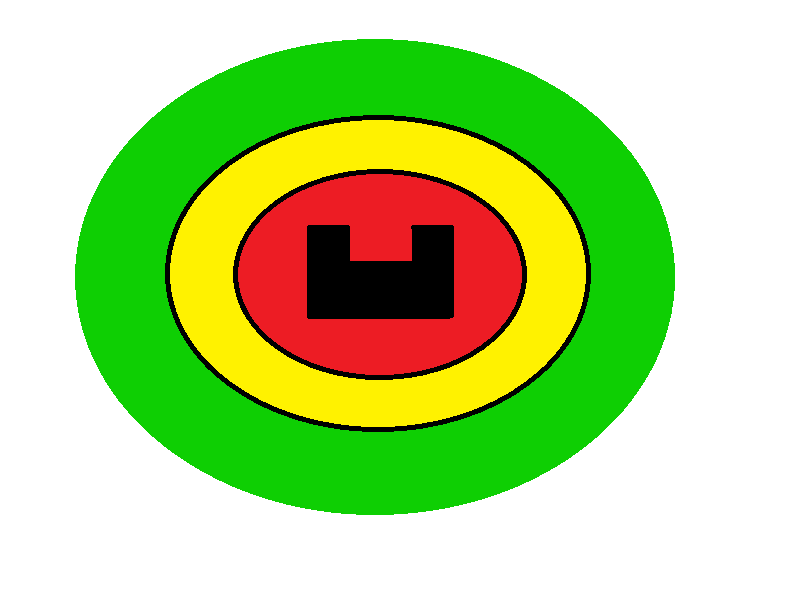
Figure x:The different areas around PICO once in an open space.
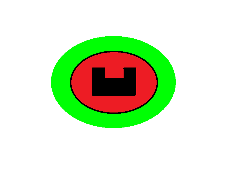
Figure x:The different areas around PICO once in a narrow space.


Motor Control

Due to investigations it was already clear that no complicated control was necessary. To make the movements of Pico slightly more smooth, a proportional controller has been implemented.
The function furthermore returns the relative distance travelled each sampling interval and saves the current velocity in X- and Y-direction and the rotational velocity in the worldnodel.
Simulation results of the hospital challenge
Two simulation examples have been made for the hospital challenge. One nominal situation and one situation where clutter objects are apparant on the map. These can be seen below.

Figure x: Simulation of Pico in nominal environment.
Figure x: Simulation of Pico in cluttered environment.


Both videos show desired behavior of the robot. In the nominal situation, the robot even succeeds to visit all the cabinets. However, in the cluttered environment, PICO's localization fails due to the environment not matching the map. This can be seen at some point when PICO is in the hallway. Below a Figure is shown with 2 consecutive location samples, the green one is an accurate guess while the red one is estimated badly.

Results of the Hospital challenge
In order to give a complete overview of the Hospital Challenge, a video compilation is made of the two trial runs, with all static objects, doors and dynamic objects included, and a nominal run with only a dynamic object and no doors or static objects from after the challenge. This video compilation can be seen in Figure x and in the link given below. In the given link the full video in high quality can be seen.
The results were as expected, due to the fact that the simulation results already showed there were flaws in the localization when the deviation from the nominal situation was too large. However, as expected, PICO is able to fully complete the nominal challenge, as can be seen in Figure x.

https://www.youtube.com/embed/D3zYT49ZT44
Evaluation of the Hospital challenge
An evaluation of the Hospital challenge is done to review the performance of the software. A division is made between improvements, which would make the robot finish the Hospital challenge, and recommendations, which would further optimize the performance.
Improvements
Localization
As can be seen in the trial runs in the Hospital Challenge, the main fault in the concept lies within the localization. As the localization is implemented, it runs every iteration and calculates the position again. As the robot reaches the area where the 'couch', 'cupboard' and 'door' are placed, the robot is unable to locate itself, even though PICO has access to its location from a previous time step, which is reliable. If the software for PICO would have been built to trust the odometry when there is an unsure localization for PICO until a new trusted location for PICO is available, this would have improved the robustness of PICO greatly. If PICO did not know its location as built now, PICO would spread particles all over the map in order to try locate itself, which causes great disturbances for the localization, thus creating a position on the map with a large error, and thus uncertain path planning.
Voorstel Gosse: As can be seen in the trial runs in the Hospital Challenge, the main issue in the concept lies within the localization. The location is determined at every iteration and the constant addition of random particles could create a close match everywhere on the map. This results in the position possibly flying around the map. This relocatization should only be done when the robot is sure that it has lost it's position.
The update of particles should take into account the relative odometry data. Particles should all be shifted with the relative movement before noise is added.
The localization is now considered to be the mean of all particles. This could be improved by including a cluster detection. When there are two locations on the map, which have a high likelihood of being the true position, this should be the output. Instead of just taking the mean of both clusters.
Furthermore, when the robot reaches the area where the 'couch', 'cupboard' and 'door' are placed, the robot is unable to locate itself, even though PICO has access to its location from a previous time step, which is reliable. When the location is reliable the LRF data can be used to validate different hypotheses. For example, pico could test if a door is closed, which could be added to the map. Pico could determine static objects, which also could be added to the map. This creates a more robust algorithm for localization, while unexpected changes are no longer disturbances to PICO, but they are considered as localization points.
Finally, the localization could be improved by adding a weighting factor to different type of objects. Walls for example are always present and if a fit can be made on a wall this should have a higher addition of probability compared to making a fit to a dynamic obstacle for example.
Path Planning
Next to this, during the Hospital Challenge, PICO is lifted and put inside the right room, which it recognized. However, the path planning was designed in such a way that PICO had to follow a list of waypoints until it got stuck. Once regaining its location in the right room, PICO's path planning intended for PICO to drive back to the waypoint on the way to the cabinet. As an improvement, the path planning should have taken into account the actual location and closest distances to different waypoints and planned its route accordingly.
Mapping
Thirdly, the localization did not project known disturbances into the map, which could have greatly helped. Adding static disturbances could increase robustness, as PICO has gathered more information of its surroundings. This could have placed the knowledge that an object, such as the 'cupboard', is in the hallway and will anticipate this now known disturbance during future encounters. This could have helped during localization in further iterations and thus strengthen the knowledge of its location.
Object Detection
Lastly, PICO bases its hypotheses of off short time periods. In order to increase robustness, PICO should test certain hypotheses, such as the hypothesis whether a static object is truly static throughout the entire Hospital Challenge or is static for certain periods of time, multiple times and should have the ability to turn certain waypoints on and off.
Recommendations
Path Planning
Since the hospital which should be solved was not large, the paths could easily be hard coded in a short time. However, when the hospital would be larger this would take significantly more time. Therefore a simple algorithm could be implemented giving a short path to the next cabinet. A suitable algorithm could be dynamic programming, which would use the absolute distance from waypoint to waypoint as costs.
Sampling Rate of Localization
As stated before, the odometry data should be used to determine the position of the robot. If this would have been done, the verification of the robot position using the laser range finder could have been sampled less frequent. This would lower the computational load.
Code Snippets
In the first code snippit it can be seen that for each waypoint, there are three possibilities. The first possibility is that the task is finished, as no cabinets are left in the list. The second possibility is that the waypoint list is empty. In this case, PICO arrives either at a cabinet or in the hallway. At the cabinet PICO will be facing it and taking a snapshot, then the desired direction is given as the opposite of the direction facing the cabinet and the cabinet is removed from the queue and a new route is determined to the next cabinet or hallway. If PICO arrives in the hallway, a new path is planned to the desired cabinet. The last option is that PICO arrives at an intermediate waypoint, where PICO stops, determines the required angle to the next waypoint and will orient itself towards it.
Waypoint Arrival decision making
In order to increase robustness of PICO, difference in expected sizes of objects, or lack of objects is to be accounted for. For example, if a static object is placed where PICO is moving, however it is not completely in its path, this snippit works simultaneously with driving towards the path, leading to a smooth motion to avoid the object. Also in corridors, PICO can use this to avoid walls effectively, while still continuing its path.
In the next code snippit, a hypothesis is checked when an object is in the circle. PICO checks whether the object is static or not, and in this snippit, PICO checks whether the object is coming towards PICO. In this case, PICO will check which quadrant the object is coming from, check whether the opposing side is free to move in, move there and as last resort will drive backwards until the object is no longer in range of PICO, or until the opposing quadrant is free to move in. This is done in order to dodge an incoming object without harm to PICO.
Deliverables
- File:Design document.pdf
- File:Presentation EscapeRoom Challenge.pdf
- File:Presentation Hospital Challenge.pdf