Embedded Motion Control 2017 Group 3 / Corridor Challenge: Difference between revisions
No edit summary |
|||
| Line 1: | Line 1: | ||
This page is part of the Embedded Motion Control [[Embedded_Motion_Control_2017_Group_3 | Group 3]] of 2017. | This page is part of the Embedded Motion Control [[Embedded_Motion_Control_2017_Group_3 | Group 3]] of 2017. | ||
[[File:EMC17-G3_CC_Corridor.png|thumb| | [[File:EMC17-G3_CC_Corridor.png|thumb|200px|right|Figure 1: Typical Corridor]] | ||
This page is about the design made from the initial design up to the moment of the the Corridor Challenge. For this challenge is PICO should drive itself through a corridor which is constructed with parallel walls, detect the first exit and take a turn. First the design steps are described, followed by notable algorithms used and | This page is about the design made from the initial design up to the moment of the the Corridor Challenge. For this challenge is PICO should drive itself through a corridor which is constructed with parallel walls, detect the first exit and take a turn. First the design steps are described, followed by notable algorithms used and their software implementation and concluding with the functioning of the code in the simulation. In figure 1, a typical corridor used in the Corridor Challenge is visible, however, the opening could also be at the left side. | ||
== Design steps == | == Design steps == | ||
[[File:Corridor sense.png|200px|thumb|right|Figure 2: LRF data used to determine distances in front, left and right of PICO]] | |||
From the requirements we designed we wanted PICO to never hit any walls, but also prevent PICO from going into deadlocks. With this decision we excluded the use of the potential field, where the walls give a distance dependent rejecting force towards PICO. Although this can be a very robust way to avoid walls, it could potentially create a lot of deadlocks problems (mostly for the maze). Instead we used a PID controller to keep PICO always in the middle of a corridor, we used sections of filtered (averaged) data from the LRF (as shown in Figure 2) as input for the PID controller. | |||
[[File:Corridor node points.png|200px|thumb|right|Figure 3: PICO aligning to the new corridor]] | |||
This controller only operates in the part of the corridor where there are walls on both sides, when PICO detects an open space the PID is be turned off and he would turn 90 degrees (left or right). After turning, PICO would | This PID controller only operates in the part of the corridor where there are walls on both sides, when PICO detects an open space on one of the sides the PID is be turned off and he would turn 90 degrees (left or right) based on the odometry data. After turning, PICO would attempt to find the two corner points of the new corridor (blue dots in Figure 3) and move to match the lengths of the pink and red line. Once PICO was in the middle of the new corridor it would move forward and turn the original PID on again. | ||
== Notable Algorithms == | == Notable Algorithms == | ||
Revision as of 18:51, 21 June 2017
This page is part of the Embedded Motion Control Group 3 of 2017.
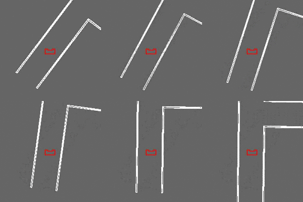
This page is about the design made from the initial design up to the moment of the the Corridor Challenge. For this challenge is PICO should drive itself through a corridor which is constructed with parallel walls, detect the first exit and take a turn. First the design steps are described, followed by notable algorithms used and their software implementation and concluding with the functioning of the code in the simulation. In figure 1, a typical corridor used in the Corridor Challenge is visible, however, the opening could also be at the left side.
Design steps
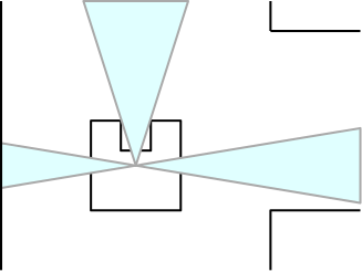
From the requirements we designed we wanted PICO to never hit any walls, but also prevent PICO from going into deadlocks. With this decision we excluded the use of the potential field, where the walls give a distance dependent rejecting force towards PICO. Although this can be a very robust way to avoid walls, it could potentially create a lot of deadlocks problems (mostly for the maze). Instead we used a PID controller to keep PICO always in the middle of a corridor, we used sections of filtered (averaged) data from the LRF (as shown in Figure 2) as input for the PID controller.
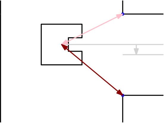
This PID controller only operates in the part of the corridor where there are walls on both sides, when PICO detects an open space on one of the sides the PID is be turned off and he would turn 90 degrees (left or right) based on the odometry data. After turning, PICO would attempt to find the two corner points of the new corridor (blue dots in Figure 3) and move to match the lengths of the pink and red line. Once PICO was in the middle of the new corridor it would move forward and turn the original PID on again.
Notable Algorithms
In this section a few algorithms used for the corridor challenge are described, together with there software implementation, to show how our code differentiated from the other groups.


