Embedded Motion Control 2017 Group 10
Group Members
| 0773865 | Tim Coerver |
| 0953808 | Pieter de Groot |
| 0970955 | Jos Terlouw |
| 0973811 | Bas Vermij |
| 0972391 | Roel Vromans |
| 0975718 | Corné van Haren |
Initial Design
Link to the PDF version of the design document: PDF
Requirements
- Software easy to setup
- Updated with one easy command, e.g. 'git pull'.
- Software can be compiled using 'cmake' and 'make'.
- One executable to start software.
- Autonomously solving the corridor challenge
- Solving the corridor challenge has to be done within 5 minutes.
- Autonomously solving the maze challenge
- Solving the maze challenge has to be done within 7 minutes.
- Avoiding collision
- Do not bump into walls or doors.
- Recognize and open a door in the maze
- There might be multiple dead ends in the maze, one of which is a door. The robot has to be autonomously open the door (by ringing a bell) to solve the maze.
- Detect corridors, corners, T-junctions and intersections
- The maze and corridor challenge consists of several, corridors, corners, T-junctions and intersections. Various algorithms created in order to detect these.
- Navigate through corridors, corners, T-junctions and intersections
- When corridors, corners, T-junctions and intersections are detected, the robot has to drive trough these. In order to do this, strategies have to be created for each of these.
- Detecting dead ends
- The maze can contain dead ends, these have to be distinguished from doors.
- Detecting maze exit
- The exit of the maze has to be detected in order to know when the maze is finished.
- Navigate open spaces
- The maze can contain open spaced, when these are detected these has to be explored by navigating trough them.
Specifications
The specifications are related to the requirements specified above.
- The time to reach the end of the maze is 7 minutes.
- The time to accomplish the corridor challenge is 5 minutes
- The robot may not be idle for more than 30 seconds.
- When the robot find a door, it rings a bell and the door will be opened manually.
- Two attempts to solve the maze are allowed. Both attempts have to be finished within 7 minutes total.
- Two attempts are allowed to solve the corridor challenge. Both attempts have to be finished within 5 minutes.
- When the robot bumps into a wall the attempt is over.
Specifications of the maze
- All walls are positioned approximately perpendicular to one another.
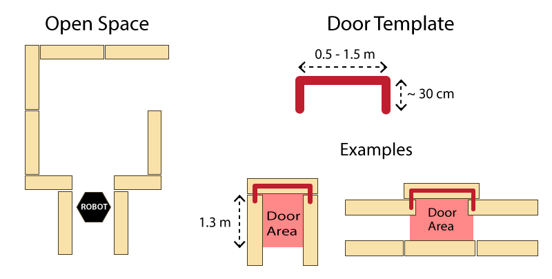
- Open spaces might occur (as depicted in Figure 1 ).
- There may be loops in the maze, which means that some walls may not be connected to other walls.
- Walls are approximately parallel.
Doors and open spaces are specified as described by Figure 1.
Functions
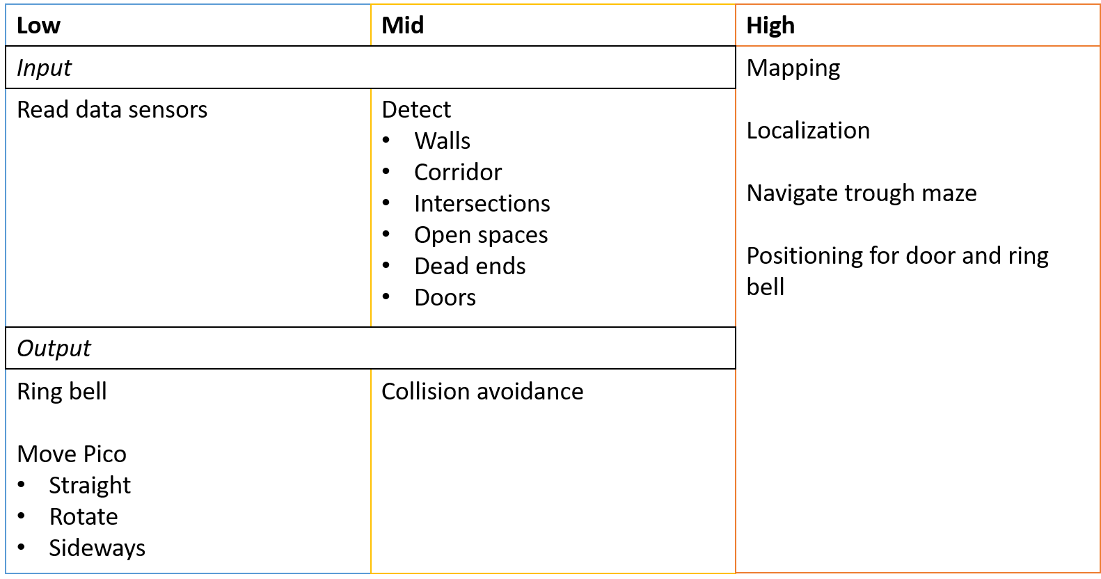
The functions are categorized in three different levels of complexity: Low, Mid and High level. An overview of the functions is given in Figure 2.
Components
The following components are accessible on the pico:
- Sensors
- Laser Range Finder (LFR)
- Wheel encoders (odometry)
- Actuators
- Holonomic Base (Omni-wheels)
- Computer
- CPU Intel i7
- OS Ubuntu 14.04
Interface
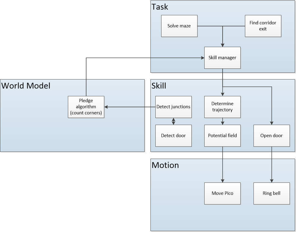
The interfaces between functions are shown in Figure 3. Here the functions are devided into: Tasks, Skills, Motion and World Model. The world model contains the functions that are used to keep track of Pico's surrounding. Tasks contains the functions on the highest level where the robot decides what it is going to do, like solve the maze. The skill block consists of all functions that make the robot perform lower level tasks such that the high level objective can be achieved. The motion block does the low level operations that make the skill functions work.
The Corridor Challenge
Potential field
Corner mapping
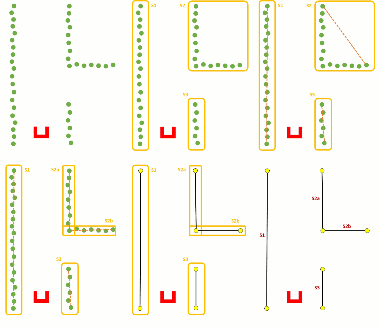
To detect corners and walls the Split and merge algorithm is used on the laser data. This algorithm contains the following procedure;
- 1. Laser data is transformed in x and y coordinates
- 2. The laser data points will split in segments
- 3. Within each segment the points between the first and last point will be check for the distance perpendicular to the line between the first and last point
- 4. If the maximum perpendicular point is above a set threshold (0.2 m), this point will set as a vertex within this segment.
- 5. Step 3 and 4 will be repeated until there are no new vertices are found.
- 6. Within each segment a line will be defined using the least squire method.
- 7. If two lines are connected with each other, the intersection will be used to define the vertex.
- 8. If there is not a connection with another line, the end point will be fitted on the line.
Challenge Result
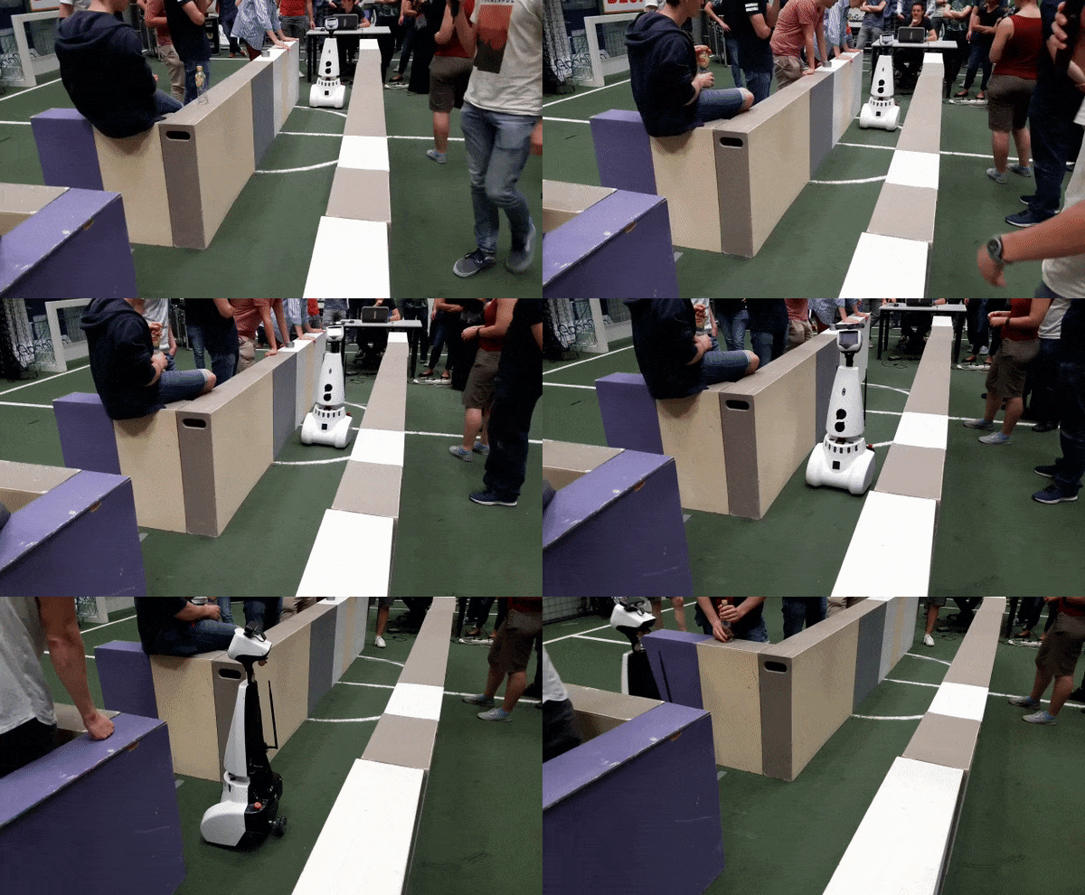
Pico managed to finish the corridor challenge in 24 seconds, this got us the third place. As can be seen in die video on the straight the Pico wobbles a lot this is due to the over reactive implementation of the potential field. Without this wobbling we would possible end up in the first place.
The Maze Challenge
Final design
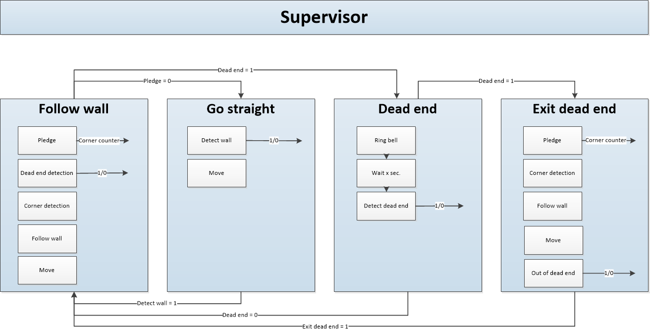
For the final desig the following stage machine is designed
Pledge
The Pledge algorithm is used to make a very simplistic global world map to solve the maze. The pledge algorithm uses relative angle movements to calculate the total rotation angle of the robot. Rotation clockwise has negative angle and rotation clockwise has positive angle. After the robot rotates pi rad, the OdometryData switches to a negative angle of -pi rad. The relative angle is in that case 2 pi rad. To compensate, 2 pi is subtracted leaving with only the relative angle. With this rotated angle, the taken corners can be calculated.
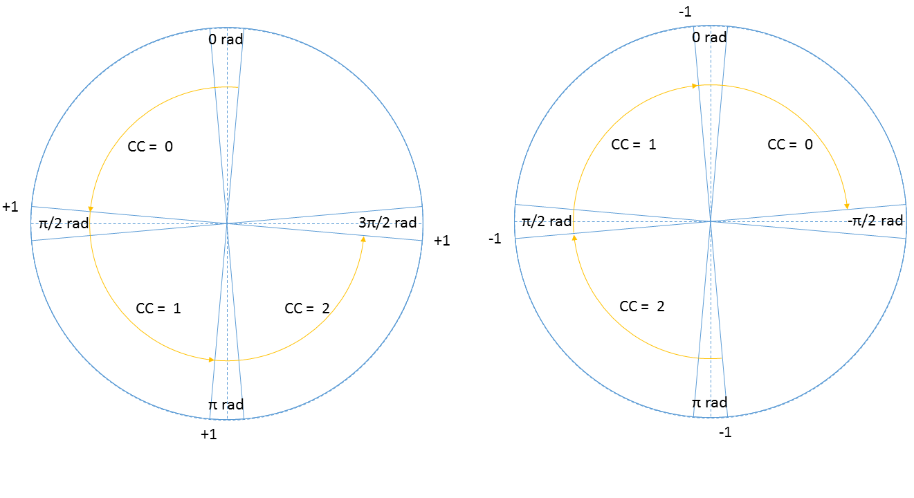
To make the pledge algorithm robust, a method is used where a corner is counted after the robot moved pi/2-delta rad and will hold this count till the robot moved another pi/2-delta rad as shown in Figure 5 (left circle). In between the robot can move freely without corners being added. The same holds for the robot rotating back where the corner counter is reduced only after the robot moved -pi/2+delta rad Figure 5 (right circle).
Result
Weekly Planning
- Final challenge
