Embedded Motion Control 2016 Group 3
Group Members
| 0976155 | Aditya Kamath | a.kamath@student.tue.nl |
| 0976940 | Amrith Vel Arul Kumar | |
| 0980790 | Alexis Siagkris-Lekkos | a.siagkris-lekkos@student.tue.nl |
| 0976467 | Ayush Kumar | |
| 0978245 | Mahmoud Al Abbassi |
Initial Design Idea
Here the first approach to the problem is presented, namely Design Document 1 that describes the initial design idea for a robot that navigates through a maze and finds the exit autonomously.
Overview
This article presents a summary of the software design to solve the following challenges with the Pico robot.
- Corridor competition: To follow a corridor and take the first exit.
- Maze competition: To solve and exit an unknown maze.
The project is divided in the following aspects:
- Requirements
- Specifications
- Functions
- Components
- Interfaces
Requirements/Specifications
For the brainstorming phase, the requirements and specifications are described in one section as the specifications cannot be determined without an introduction to the robot hardware. The requirements of the robot are as follows:
- The robot should not stand still for more than 30 seconds
- The robot should not collide with the walls
- The robot should solve the undisclosed maze and exit within 5 minutes
- The software should store the maze as a map and the robot should be able to revert back to the last known state/position in case of any error.
- The robot should be able to distinguish between the door and dead ends and send out a request to open the determined door
- The robot should determine if the maze is solved and should stop accordingly
Functions
Functions are divided into low, mid and high level. High level functions are not required for corridor challenge.
Low level
| initialization: | Initialization of sensors, actuators |
| read_inputs: | Read laser (LRF) and encoders (walls as reference) |
| drive_forward: | accelerate, decelerate can be separate sub-functions |
| drive_sideways: | Motor control for sideways motion |
| left_turn: | Turn 90o left( doesn’t necessarily need to be at standstill) |
| right_turn: | Turn 90o right |
| U_turn: | Turn 180o left |
| standstill: | Stay at the same position with zero speed, for instance when it waits for the door to open |
Middle level
| get_distance: | Measure the distance to an obstacle (wall, door, anything) |
| avoid_collision: | Keep a safety distance from walls (possible sub-functions: slow down when you\’re close, completely stop when you\’re ready to crash) |
| kill_switch: | Polling for the manual switch to shut the robot, when needed by us |
| finishing_line: | A function to identify the finishing line and shut down the robot (possible options: use kill-switch or detection of being far away from any wall i.e. no walls in front or to the right/left) |
| find_gaps: | Identify all possible passages, corridors (straight, right, left), identify crossings |
| dead_end: | Check if the robot is at a dead end and make a U-turn or return_to_last_crossing |
| return_to_last_crossing: | If the robot meets a dead end (this may be integrated into the decision routine) |
| door_check: | Check if there is a door at a dead end ( possibly just check for height is enough, because the doors are shorter than the walls OR just ask for door to open and wait to see if it gets a response) |
High level
| opt_decision: | The robot decides what its next move (move forward, turn, stand still) will be, based on the chosen algorithm for the optimal decision for the maze (algorithm will be decided later on, possible algorithms: A*, Tremaux), on the mapping and on the current position (recognize scenario e.g. Dead end) |
| reference_path: | Create the desired path for the robot, from one point to another (especially for cases that we know exactly where the robot must go, already mapped paths) |
| random_decision: | Take a random decision the first time the robot is at a junction |
| mapping: | Build a map according to the obstacles(walls) or empty spaces (passages, corridors) identified by the laser |
| check_position: | Check if the robot has already been in this position, otherwise store position (starting point=reference point) |
| store_position: | Store the current location of the robot in the map (if not already stored), to create a path and to avoid visiting same places twice |
Components
PICO includes multiple components that can be classified in three groups as: Sensors, Actuators and Computer.
- Sensors:
- Laser Range Finder (LRF): The LRF situated on PICO can determine the distance to an object. The technique consists of shooting a light pulse towards an object, receiving it, and measuring the time it takes. This sensor will be useful to locate walls, corners and doors.
- Wheel encoders (odometry): The encoders will provide us with the speed of the wheels which can be used to control PICO based on the provided data.
- Actuators:
- Holonomic base with omni-wheels
- Pan-tilt unit for head
- Computer
- Intel I7
- Ubuntu14.04
Interfaces
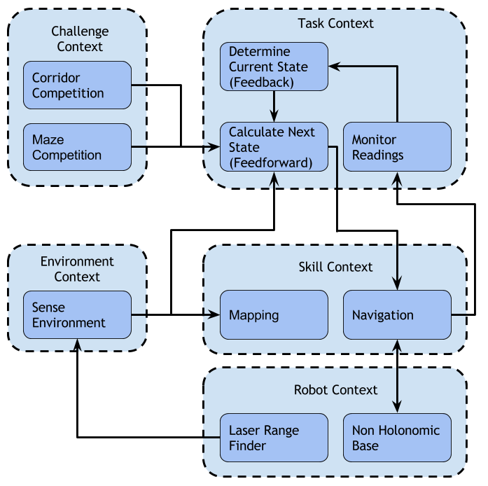
This section describes the interfaces between the following abstractions:
- Challenge context: Describes the goal of the challenge
- Environment context: Describes the environment sensed by the robot
- Robot context: Describes the robot hardware and sensor readings
- Skill context: Describes the robot\’s skill-set
- Task context: Describes the decision-making abstraction
The interfaces between the above abstractions can be seen in the diagram below:
