Embedded Motion Control 2016 Group 2: Difference between revisions
| Line 189: | Line 189: | ||
The discrete time model of the global position that was mentioned before is being used as the prediction model for the global position. The input data are the forward speed, sideward speed and rotational speed calculated by the code and giving to ''io.sendBaseReference()''. Combining the prediction model and the input data will give an estimation of the global position of the robot. To get a proper estimation of the global position, the measurement noise and the process noise need to be modelled correctly. The measurement noise can be based on sampling experimental data and deriving the statical properties. The covariance matrix <math>R</math> of the measurement noise can be calculated by, | The discrete time model of the global position that was mentioned before is being used as the prediction model for the global position. The input data are the forward speed, sideward speed and rotational speed calculated by the code and giving to ''io.sendBaseReference()''. Combining the prediction model and the input data will give an estimation of the global position of the robot. To get a proper estimation of the global position, the measurement noise and the process noise need to be modelled correctly. The measurement noise can be based on sampling experimental data and deriving the statical properties. The covariance matrix <math>R</math> of the measurement noise can be calculated by, | ||
<math>R_{ij} = \frac{1}{N-1}\sum_{k=1}^{N}(x_i-\bar{x}_i | <math>R_{ij} = \frac{1}{N-1}\sum_{k=1}^{N}(x_i-\bar{x}_i)(x_j-\bar{x}_j).</math> | ||
The covariance matrix <math>Q</math> which represents the process noise is not as straightforward as the covariance matrix for the measurement noise. It is being used to filter the errors in system model. Therefore the covariance matrix <math>Q</math> is being treated as a tuning parameter. | The covariance matrix <math>Q</math> which represents the process noise is not as straightforward as the covariance matrix for the measurement noise. It is being used to filter the errors in system model. Therefore the covariance matrix <math>Q</math> is being treated as a tuning parameter. | ||
The extended kalman filter follows the following scheme to estimate the global position of the robot. <br/> | The extended kalman filter follows the following scheme to estimate the global position of the robot. <br/> | ||
Revision as of 16:32, 15 June 2016
Group Members
| 0779760 | Ilias Aouaj |
| 0818316 | Florian Bastiaens |
| 0755206 | Yannick Knops |
Goal
The goal of the maze competition project is to create software that lets the pico robot solve a maze and drive through it fully autonomous as fast as possible. In this maze there will be certain obstacles that the robot has to overcome during the solving of the maze, for example doors, open spaces, dead ends and loops in the maze.
Group progress
Week4
In this week a major shift occured in our group. 2 group members left, and what we initially did was too complex. We decided to start from scratch. Completing the corridor challenge was our main priority. We decided to use potential only in the x-direction to keep the robot positioned between the walls and avoid collisions. We didn't expect any problems in y-direction, so the speed in y-direction remained constant. A corridor detection was implemented based on the LRF data left and right from the robot.
Week5
In this week we combined the potential field that is used to avoid collisions and keeps the robot between the corridor walls with corridor detection to obtain 3 states for the robot. One where a corridor is recognized on the left side with translational motion set to zero and where it keeps rotating until it faces the direction of the detected corridor. The second state is almost exactly the same as the previous one, it differs as the recognized corridor is on the right side of the robot. The third state is where it moves through the corridor with a constant speed in the y-direction, an alternating speed in the x-direction based on the potential field and rotational speed set to zero. This was also the week of the corridor challenge, which we succeeded on the first try. The only point was that it moved to slow in the y-direction which is due to the unchanged parameter for the speed "Vy" we used during the tests. On the same day we had our initial presentation, due to some difficulties some slides were missing.
Initial design
Initial Idea
This is the report for the deadline of 27-04 about our initial thoughts of how we will structure the software for a autonomous maze solving robot.
Requirements
Based on the restrictions of the maze competition and the conditions that have to be met, the following requirements are set:
- The maze has to be solved by the robot autonomously within a given timeframe
- The robot has to avoid collisions with the walls and other obstacles
- The robot has to recognize doors
- The robot cannot be idle for a certain time
Functions
To keep a well structured overview of the functions, they are divided into two categories: the basic
hardware functions and the skills. The basic functions are the lowest level and they represent the
hardware. The skills are combinations of basic functions to complete more difficult tasks
The basic functions are:
- Translation using omniwheel actuators
- Rotation using omniwheel actuators
- Scan using the Laser Range Finder (LRF)
- Scan distance driven using odometry
These functions can then be combined to create the following skills:
- Drive:
- The robot moves using this skill. It uses the basic functions driving straight and turning. It
- also uses another skill, collision detection.
- Collision detection/prevention:
- The collision detection skill prevents the robot from hitting walls while navigating through the
- maze. It provides live feedback control from the LRF by detecting the distance to the walls
- and correcting the robots movement.
- Junction recognition:
- This skill is used to recognize junctions and corners in the maze. When the robot is moving
- through a corridor, the presence of a junction or corner can be determined from the data of the
- LRF. This data needs to be processed to make the robot aware of the junctions and corners.
- Mapping:
- This function maps the corners and junctions of the maze as nodes and corridors. The function
- is essential for preventing loops while solving the maze. This skill depends on the Junction
- recognition skill.
- Localization:
- This skill will locate the robot with respect to the maze. This skill will probably use a combination
- of the LRF and odometry data to determine a location in the map created with the
- mapping skill.
- Recognizing doors:
- As previously described, the robot should be able to open doors by beeping in front of them.
- Therefore the system has to recognize a door to prevent beeping at every obstacle and thus
- wasting time.
Specifications
Specifications related to the requirements are estimated in this section.
- Two attempts are allowed within a total time of 7 minutes.
- The jury decides if a robot bumps into a wall or obstacle. If so, the attempt is over.
- The robot has to recognize doors. Using a sound signal, the door can be opened.
- If the robot is idle for more then 30 seconds, the attempt is over
Components
For this project, the robot named pico will be used. The hardware that pico contains can be divided in the part below:
- Actuator:
- Holonomic base with omni-wheels
- Sensors:
- Laser Range Finder (LRF)
- Wheel encoders(odometry)
- Computer:
- Intel i7
- Running Ubuntu 14.04
Interfaces
The way the software works can be seen in the figure below.
This is the example of
the care robot and it is to a large extent similar to this project.

The software can be divided in 5 contexts:
- Challenge context:
- The challenge context is the goal that needs to be accomplished
- Skills context:
- The skill context contains the skills that are needed accomplish the goal
- Task context:
- The task context contains decisions that have to be made. For example which turn to take.
- Robot context:
- The Robot context contains the sensor and actuators of the robot.
- environment context:
- The environment context contains the data where the robot is with respect to the direct environment, for example the walls and doors, and with respect to the maze.
Final implementation
Detection
Landmark detection
To make decisions of which corner to take and which route to follow, landmarks like T-junctions and crossings have to be detected.
In order to do this, each standard crossing has is given an landmark number.
When detection sees a landmark, it detects features of the landmark and assigns the detected landmarks number to a variable that is named object.
This variable is then read by the planning block.
Based on the stored object number, the planning block can make a decision based on the object number.
Below are some explanations of how the landmarks are detected.
Dead end detection
When at least 95% of all LRF points is smaller than a predefined range, detection decides give variable object the number that corresponds with a dead end.
This results in the dead end protocol to be activated. In this protocol Pico stops 0.4m in front of the dead end wall, beeps, and waits 5 seconds. After these 5 seconds, it looks if a door is opened or if it still is an dead end.
If object number still shows dead end, Pico turns 180 degrees and continues to drive. If a door was opened, Pico will continue the new path.
Side door detection
limited range open-space detection
To more robustly detect possible corridors, a variable limited LRF range was used. By limiting the LRF range, possible open spaces which can indicate corridors can be detected, which can be seen in the figure below.

The picture shows the limited LRF range of Pico before a crossing. The grey area is where all the limited LRF points are equal to the set maximum range. The orange area is when the LRF data detects a point within the limited-LRF data.
The open space detection looks at all the limited range data in a loop from right to left anti-clockwise and determines when a high number of consecutive points are equal to the limited range, this area is an open space, thus a potential corridor.
In the figure above this can be seen as the gray area. To prevent any small gaps to be detected, a minimum amount of conclusive points has to be detected in order to label it an potential corridor.
Each time the potential corridor is detected an x and y reference in the middle of the potential corridor at max range is stored. The first one detected is always saved as the first reference, the second one detected as the second reference etc, moving from right to left. This is also indicated with the numbers in the open-spaces in the figure above.
When no open space is detected, for example in a dead end, the reference point is placed directly in front of Pico. When driving in an actual open-space, The maximum range of the LRF data is increased so, it can again detect potiential corridors.
If a high number of points are still above the increased maximum range, the reference point is is placed directly in front of Pico.
Planning
Localization
Being aware of the global position of the robot is critical for mapping and also useful for the motion of the robot. The global position of the robot is formulated as, [math]\displaystyle{ \begin{bmatrix}
x\\
y\\
\theta
\end{bmatrix} }[/math]. The figure below shows a graphical representation of the global position.

Discrete time model
With help of goniometric properties, the discrete time model of the global position of the robot is as follows,
[math]\displaystyle{ \begin{bmatrix} x_k\\ y_k\\ \theta_k \end{bmatrix} =\begin{bmatrix} x_{k-1}+V_x\Delta{t}\cos(\theta_k)-V_y\Delta{t}\sin(\theta_k) \\ y_{k-1}+V_x\Delta{t}\sin(\theta_k)+V_y\Delta{t}\cos(\theta_k) \\ \theta_{k-1}+\omega{\Delta{t}} \end{bmatrix} }[/math].
Extended Kalman filter
Since the odometry data is unreliable for a long run a Kalman filter is applied to minimize the error in the global position of the robot. The following is needed for a Kalman filter in context of the robot:
- Prediction model of the global position.
- Input data.
- Odometry data.
- Process noise and measurement noise.
The discrete time model of the global position that was mentioned before is being used as the prediction model for the global position. The input data are the forward speed, sideward speed and rotational speed calculated by the code and giving to io.sendBaseReference(). Combining the prediction model and the input data will give an estimation of the global position of the robot. To get a proper estimation of the global position, the measurement noise and the process noise need to be modelled correctly. The measurement noise can be based on sampling experimental data and deriving the statical properties. The covariance matrix [math]\displaystyle{ R }[/math] of the measurement noise can be calculated by,
[math]\displaystyle{ R_{ij} = \frac{1}{N-1}\sum_{k=1}^{N}(x_i-\bar{x}_i)(x_j-\bar{x}_j). }[/math]
The covariance matrix [math]\displaystyle{ Q }[/math] which represents the process noise is not as straightforward as the covariance matrix for the measurement noise. It is being used to filter the errors in system model. Therefore the covariance matrix [math]\displaystyle{ Q }[/math] is being treated as a tuning parameter.
The extended kalman filter follows the following scheme to estimate the global position of the robot.

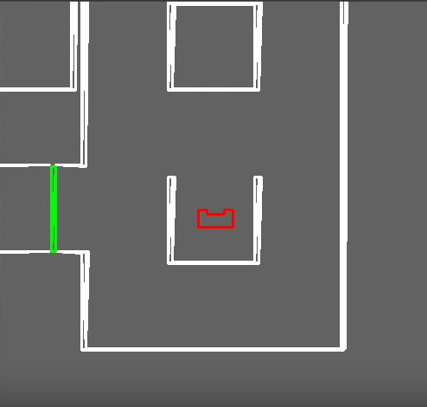
Maze Challenge
The maze itself can be seen in the figure below.

maze challenge attempts
Unfortunatly we didnt pass the Maze challenge itself. The first attempt the robot recognized doors everywhere and the robot eventually collided sideways in a wall. The second attempt the robot turned right and then another right and then continued the corridor untill it passed the door on the left and turned right again. However, it then drove close to the wall again, stopped and then bumped the wall again.
what went wrong
fixing the code
Below is a video where we do pass the Maze Challenge in the simulation.
 |