Embedded Motion Control 2015 Group 2
Go back to the main page.
Group Members
| Name: | Student id: | Email: |
| Groupmembers (email all) | ||
| Wouter Kuijpers | 0864565 | w.j.p.kuijpers@student.tue.nl |
| Carel Wechgelaer | 0874762 | c.a.wechgelaer@student.tue.nl |
| Natalia Irigoyen | 0929175 | n.irigoyen.perdiguero@student.tue.nl |
| Stephanie Dávalos | 0925756 | s.davalos.segura@student.tue.nl |
| Georgi Hristov | 0931293 | g.s.hristov@student.tue.nl |
| Paul Padilla | 0926256 | g.p.padilla.cazar@student.tue.nl |
| Garbí Singla | 0932046 | G.Singla.Lezcano@tue.nl |
| Tutor | ||
| Luis Ferreira | n/a | L.F.Bento.Ferreira@tue.nl |
Planning
Week 1 (22/4 - 29/4)
Problem formulation, ideas on design as well as task allocation. Additional work on :
- Intitial design document
- Presentation preparation
- Ubuntu set-up with all required software running
- C++ tutorials
Week 2 (29/4 - 06/5)
- Allocation of team roles in the project
- Finish of presentation
- Finish of C++ tutorials
- Meet tutor and discuss design
- Use his feedback to improve design document
Week 3 (06/5 - 13/5)
- Presentation of initial design
- Revision of design document
- Corridor completion task :
- Tasks and code structure breakdown
- Work allocation
- Testing on the actual robot :
- 11/5 - Due
- 12/5 - Due
Week 4 (13/5 - 20/5)
Initial Design
Goal
Design and implement software for the PICO robot, such that the robot is able to find the exit of the maze as quickly as possible and in a fully autonomous way.
Requirements
- Use the PICO robot to solve the “A-Maze-ing challenge.”
- The PICO robot should reach the end of the maze in the shortest time.
- The PICO robot should operate fully autonomously; after starting the robot it should make all decisions about navigating autonomously.
- The operation of the PICO robot should be independent of the maze configuration.
- During operation the PICO robot should not collide with anything, e.g. walls, doors, robots and humans.
- The software used to interface with the PICO robot should contain a software-based kill- switch to allow manual termination of the robot.
Functions
- Basic - start, stop, move forward, turn
- Navigation - maze solving algorithms and optimal path calculation
- Maze mapping - survey the area, search for doors
- Safety - keep minimum distance from walls, respond to kill-switch
Components and Specifications

- Robot Context - Low-level specifications of the PICO Robot. The robots hardware abstractions layer which takes care of all low-level sensing- and actuation-capabilities of the robot (holonomic base, odometry sensors, LRF).
- Skills Context - Contains the above mentioned robot functionalities - navigation, perception, mapping, surveying, terminating.
- Environment Context - Semantic maze model.
- Task Context - Controls the execution of the robot’s skills depending on the challenge and the environment context. The task context is divided into three major parts :
- Task control feedback: Depending on the information received from the task monitor contributes in controlling the robot skills, keeping the minimum distance to walls contraints and taking autonomous decisions.
- Task control feedforward: Depending on the state and the goal of the challenge contribute in controlling the robot skills and help construct the semantic maze map.
- Task monitor: Monitors the execution of the skills, interprets sensor readings and sends this information to the task control feedback which in turn decides upon a new control action.
- Challenge Context - Contains all the information about the maze-challenge at hand such as the rules of the game and goal of the game.
Interfaces
- Skill context – Robot context: This interface takes care of sending commands to low-level hardware and returns sensor signals.
- Challenge context – Environment context: This interface takes care of assumptions about the maze and goal approach.
- Task context – Environment context: This interface takes care of providing the correct information to the task context in order to make decisions based on the maze map.
- Task context – Skill context: This interface takes care of the skill selection based on both the contribution of the task control feedback and task control feedforward.
- Challenge context –Task context: This interface takes care of providing the goal of the challenge context to task context, in order to make decisions to aim for the goal of the challenge while adhering to the rules of the game.
- The Challenge context also provides the interface to control the robot from the outside of the field, this involves commands to start and stop the robot and provide information about the current status of the robot in the maze.
Files
- Design Document - File:Design Document.pdf
- Initial Presentation - File:Initial Presentation.pdf
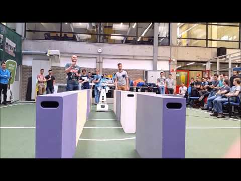
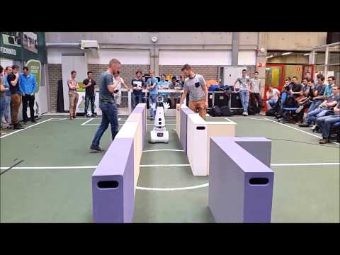
Corridor Competition
On the 13th of May 2015 the Corridor Competition was scheduled. Videos of our both attempts to reach the finish of the corridor can be viewed by clicking on the two pictures below
 |
 |
Analysis First Try
- Keeping Minimum Distance-algorithm: performs oké, an initial limit estimation was used ensuring that the robot keeps a safe distance to the wall.
- Turning: after making a 90 degree turn the coordinator presumably switched back to normal mode, then it saw a new end of the corridor on the left and wanted to turn immediately. In this case the coordinator had to be overwritten by first driving forward without the possibility of again turning.
Analysis Second Try
- Keeping Minimum Distance-algorithm: performs oké, an initial limit estimation was used ensuring that the robot keeps a safe distance to the wall.
- Turning: we do not know what went wrong here. So far we have also not succeeded recreating the same behavior in the simulator.
Lessons Learned
- A new algorithm is needed for keeping the minimum distance to the wall, this algorithm causes a large variation in the robot's orientation. In designing this new algorithm use can be made of the algorithm as a basis.
- A new algorithm is needed to detect possible turns or, in the real maze, intersections and T-junctions. In designing this new algorithm use can be made of the algorithm as a basis.
Composition Pattern
On the 27th of May the Composition Pattern presentation was given in the EMC lecture. In this presentation the (slightly revised) Task-Skill-Motion-framework was presented and the mapping from this to the Composition Pattern Hierarchy; which is shown in the picture below.

The slides of the presentation can be found here: * Design Document - File:Presentation 27052015.pdf
Final Design
(Mapping the Maze) Low-Level Feature Detection
(Mapping the Maze) Feature Detection
(Mapping the Maze) Robot Position

The main function of the Global Robot Positioning System (GRPS) is to provide the location of Special Situations after visiting them and "predict" the location of Special Situations when encountering one. The Global Position of Special Situations is of great importance in building a topological maze map. This functionality was fully integrated in a robotPosition-class in the C++-language. This class mainly contains the following elements, a more detailed explanation/description is given after this short one:
 * initialDistance - this method determines the distance to the next perpendicular wall.
 * readyForCorner - this method executes all the functionality when a Special Situation is detected for the first time.
 * Cornering - this method is active when the robot is turning and keeps track of the robot's position during it.
 * CorneringFinished - this method  executes after a corner has been completed. It makes sure that the LandMark position in the (GRPS) is updated as well as PICO's own position.
Some remarks about definitions: a special situation is defined as being a: corner (both to left and right), X-junction, T-junction, Dead-End, U-Turn. In the function-names above Cornering is being used, this method actually refers to turning of the robot it activates whenever the robot is changing orientation. Also throughout the next explanation the term LandMark will be used to indicate the representation of a Special Situation in the Maze Map. The global position of the robot will be represented by a (x,y)-coordinate where the (positive) x-direction is oriented along the East and the (positive) y-direction is oriented along the North.
Detailed Explanation/Description - Corners
Now we will give a more detailed explanation/description of the Global Robot Positioning System (GRPS)-class, this will be done using following the robot throughout a sample maze presented in the picture to the left. The following functionality is executed during its execution
- The Robot is initialized at Position 1 where first the initialDistance-method determines the distance from Position 1 to the perpendicular wall in front of the robot which is denoted by A. We store this distance in StoredDistance
- The Robot then starts driving, at some point it will reach Position 2, where the method readyForCorner will be triggered by the detection of a Special Situation. At this point the distance from Position 2 to the perpendicular wall (A) in front of the robot is determined and stored in LeftInCorridor. Knowing the orientation of the robot (which is North when starting by definition) we can find the current position of PICO by adding the distance
[math]\displaystyle{ StoredDistance-LeftInCorridor, }[/math] to the y-coordinate. E.g.: the robot starts at (0,0) facing North, if then StoredDistance = 5 [m] and after arriving at Position 2, we find LeftInCorridor = 1 [m], we know that Position 2 is located at (0,4) with PICO (still) facing North. - As the distance from the mid-point of the Special Situation (which will be the Global Position stored in the LandMark) to the point where the Special Situation is detected Position 2 is quite constant we can now estimate the Global Position of the LandMark. (This is also represented at Position 6) E.g.: using the previous example and the fact that the distance from the mid-point of the Special Situation to the point where the Special Situation is detected is 1 [m], we estimate that the LandMark is at (0,5).
- A side from estimating the global position of the LandMark, the readyForCorner-method also stores the odometry data in StoredOdometry of the robot at Position 2 is stored in method, the General Coordinator then starts the execution the Cornering at the Special Situation.
- During turning the CurrentOdometry is compared to the StoredOdometry in the Cornering-method, if the orientation of the robot changed 90 degrees in the correct direction (turning left or right) the distance from Position 3 to the perpendicular wall (B) in front of the robot is determined and stored in StoredDistance.
- When the General Coordinator recognizes that the Special Situation has ended the CorneringFinished-method is ran. This method adds the difference
[math]\displaystyle{ CurrentOdometry-StoredOdometry }[/math] to the global position of the PICO robot. Also the position of the LandMark will be determined more precise (hence not an estimate anymore): in this case the x-coordinate determined before turning (Position 2) and the y-coordinate after turning (Position 3) will be used to form the global position of the LandMark will be stored in the Map. E.g.: using the previous examples and the fact that the difference [math]\displaystyle{ CurrentOdometry-StoredOdometry }[/math] is 1.5 [m] in both directions the LandMark position which will be saved will be (0,4+1.5) = (0,5.5).
- Once the robot detects the Special Situation of Wall b the algorithms executes from step 2 above. Note that after this first turn the orientation of the robot has changed, note that the distance [math]\displaystyle{ StoredDistance-LeftInCorridor, }[/math] will now be added to the x-coordinate. This change in orientation will also be applied to the estimate of the LandMark-position in step 3.
Maze Map
In our design we decided to build a semantic map using a topological tree structure. To achieve this, we store each special situation in the maze in an array structure with unique identifiers and characteristics. The array entry for a single special situation has the following information inside it :

Solving the Maze
Global Coordinator

The working of the General Coordinator is described in the flowchart given in the figure on the left.
First, the robot is initializing his parameters. Also the robots position is initialized. Then, the robot is reading the Laser Range Finder (LRF) data, which is first checked on safety. If the robot is too close to a wall, the safety limit is breached and the robot moves backwards for 2 seconds before it continues with solving the maze.
If safety is not breached, the robot is driving forward until a ‘Special situation’ occurs. A special situation is defined as a corner, T- or X-junction, a possible door and an open space. If a corner occurs, the navigation of the robot makes the turn. When the turn is completed, the robot first checks if the corner was a U-turn. Then, the mapping updates the world map and the global position and the facing, e.g. north, west, south, east, of the robot.
Another option is that there is a T- or X-junction. In this case, the solving algorithm is used to determined which path to take. After the decision is made, the robot completes the action. The mapping updates the world map and robot positioning afterwords to keep track of all paths taken.
It is also possible that a dead-end or a possible door in a straight corridor occurs. For both situations, the possible door has to be checked. Therefore, the robot has to stop and send an acoustic signal to request the door to open. Finally, after waiting for 7 seconds after the request is send, the door can be evaluated. If the possible door opens, the robot has to go through the door and update his mapping. If the door stays closed, mapping is done to prevent checking the door twice. Then, the robot continues forward for a possible door in a straight corridor. If the closed door was in a dead end, the robot rotates 180 degrees and continues forward.
The last situation is the open space. For the open space situation, the range of the LRF is increased to detect walls at every moment. Then, the target of the potential field can also be set and navigation can still perform his actions. When the open space is completed, the range is reset to his original value.
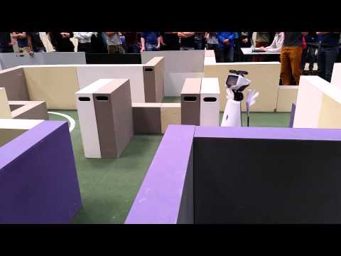
Maze Challenge
On the 17th of June 2015 the Maze Challenge was scheduled. The maze which has to solved is shown in the pictures below.
 |
 |
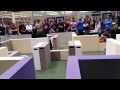
Videos of our both attempts to reach the end of the maze can be viewed by clicking on the two pictures below
Videos currently are uploaded
 |
 |
Analysis First Try
- The code we used was adjusted at many places without testing. Therefore, the robot made wrong decisions at some points. In the beginning the robot already had a collision with a wall. But after the collision, the safety algorithm made the robot to drive backwards and continue the maze challenge. Then, at the T-junction with the door, the robot chose to go forward, which was also implemented in our algorithm of the solving. Then, when the robot did the T-junction for the second time, the dead end was not recognized and therefore, a possible door was not checked.
Analysis Second Try
- For the second try, the code of the test time, the day before, is used. As there were some bugs in there, the robot was not able to take the turn and proceed to the open space. Therefore, the robot was making loops. At the X-junction, the potential field placed the target at the wrong point which leaded a turn of 360 degrees.
- In the end, our team thinks that the code of our first trial was able to perform the maze challenge successfully when the door is open. Unfortunately, during the maze challenge, we chose for the safe version.