Embedded Motion Control 2015 Group 11
Group Members
| Name | Student number | |
|---|---|---|
| Changjie Guan | 0927222 | c.guan@student.tue.nl |
| Yang Xu | 0918430 | y.xu.1@student.tue.nl |
| Bolin Zhao | 0925735 | b.zhao@student.tue.nl |
| Zhe Zhao | 0815651 | z.zhao@student.tue.nl |
| Fei Chen | 0923761 | f.chen@student.tue.nl |
| Yizhou Ye | 0925611 | y.ye@student.tue.nl |
| Yiran Liu | 0843177 | y.liu.1@student.tue.nl |
Introduction
Task and goal: Find way out of maze as fast as possible.
Requirement
The requirement analysis base on the problem statement and divide in different level of important as ‘must’,’should’,’could’ and ‘wont'
- the robot must can get out of the maze
- the robot must take action by itself
- the robot should get out of the maze as soon as possible
- the robot won’t hint the wall
Functions
Ensure all the requirements can be meeted.
- Move forward and backward, turn around
- Detect the doors
- Detec the distance between the front wall and the robot
- Remember the path and and the door, grid the path and store it with 0 or 1, representing the pass available or not respectively.
- Each step, select a direction where is available. If the current grid has not been recorded, record it and move on. If the current gird has been recorded as well as its surrounding grids, randomly choose a grid from recorded and move on. If all the maze has been searched, the robot must go out the maze.
Activity model
Behavioural model
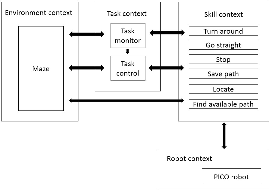
Behavioural model:
- Environment context
- Task context
- Task monitor
- Task control
- Skill context (updated to latest version)
- Find minimum value of sensor (“index”)
- Save data (including map, robot situation, etc.)
- Calculate the location and situation of robot (“update”)
- Align the robot coordinate system (Feedback angle)
- Turn around & J-turn
- Judge the robot is in the center of the road
- Check and judge cross
- Check exit (Leave the maze)
- Check dead end (J-turn)
- Make the robot back to the center of the road (Feedback location)
- Robot context
Structure Model
Function block – Behaviour and Structure
Ten functions:
- Find minimum value of sensor (“index”)
- Judge the robot is in the center of the road
- Save data (including map, robot situation, etc.)
- Check and judge cross
- Calculate the location and situation of robot (“update”)
- Make the robot back to the center of the road (Feedback location)
- Align the robot coordinate system (Feedback angle)
- Turn around & J-turn
- Check exit (Leave the maze)
- Check dead end (J-turn)
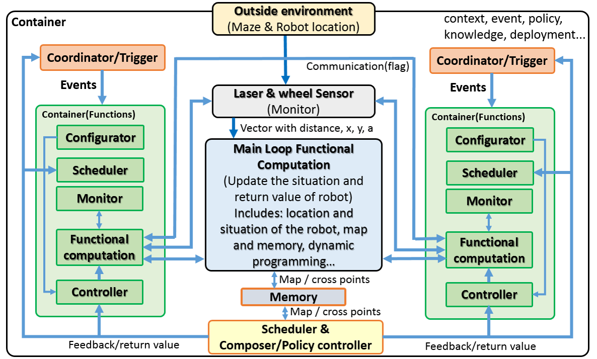
To be more specific, the structure model will be decoupled into Composition Pattern (5Cs). Below we describe how the 5Cs have been decoupled in the design of the depicted components.
5Cs:
- Computation: this is the core of a system's functionality, and it implements the domain knowledge that provides the real added value of the overall system.
- Configuration: this brings data towards the computational components that require it, with the right quality of service. These aspects can be configured by setting the values of a set of parameters definded in the components implementation.
- Coordination: Coordination components are in charge of starting and stopping the computational components of a composite.
- Communication: Communication deals with the exchange of data.
- Composition: the design concern of Composition models the coupling that is always required between the four "Cs" explained above.
Firstly, the structure model is obtained in system level. Secondly, the lower level composition patterns of the coordinator and the computation blocks (Navigation and Motion control) are shown respectively.
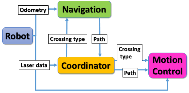
This is the highest level of the composition pattern in our design. In this composition pattern, Navigation and Motion Control are two computation components. The blue arrays show the communication between each components. The coordinator gets the setting values from configurator which is not shown in the below figure. The robot gives two kinds of data, laser data and odometery, as the inputs of the system. The laser and odometry data goes to coordinator and navigation block respectively. Navigation block save and update the map. In the other words, it saves all the data about the passed path, crossings (type, location, decision) and doors (location, decision). According to the data above, Navigation calculates the next optimal path, which becomes the input of the coordinator. The coordinator analyses the crossing type and also passes the possible next path to the motion control block.
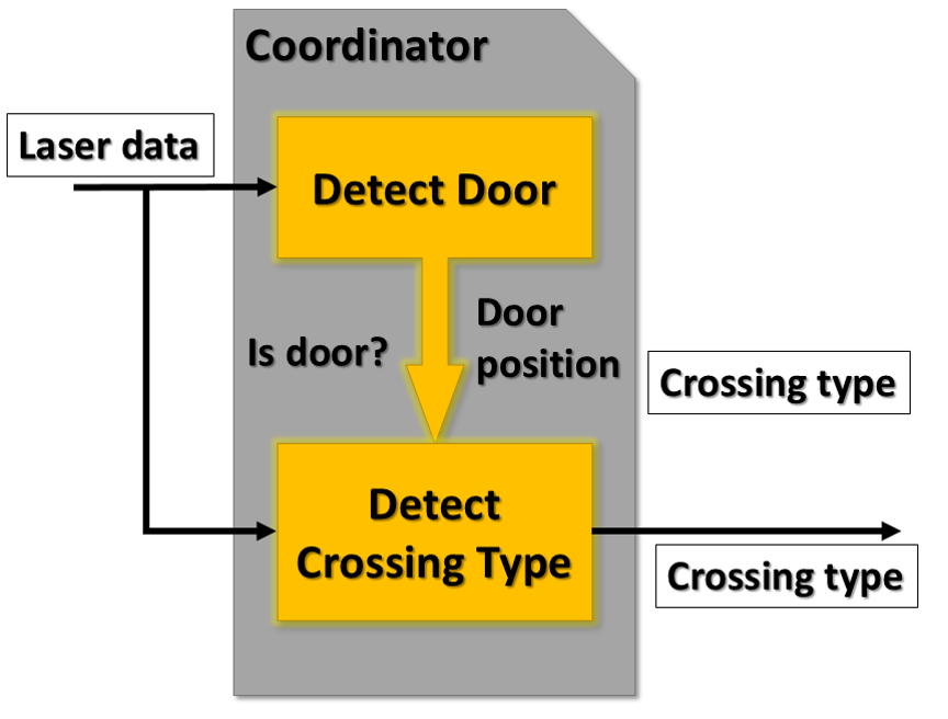
There are two computation components in the coordination block. One is the algorithm to detect the door, and the other is to detect the crossing type. Both computation components use laser data (distances and angles) as the input. For detecting door, the algorithm generates result that tells if there is a door and the location of the door. It is possible and reasonable to treat doors as crossings, and the only difference between doors and real crossing is the detecting algorithm. In this case, we could make full use of the door detecting computation component. With the information of the door (for example, it is on the left/right/front, and the distance between robot and the door), the algorithm of detecting crossing type could analyse the respective crossing type. In a result, crossing type detecting not only check the crossings, but also transfer the data of doors into crossings. Again, in this diagram, all the arrays represent the communication. There are coordinator and configurator for the whole coordinator block, but not shown in the figure.
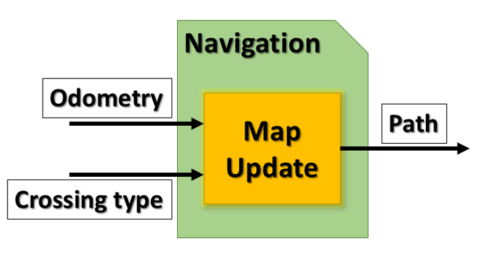
The main computation component here is to save the passed path and update the map. It uses the odometry data and crossing type to memorize the location of the passed door/crossing, the crossing type, and the chosen decision (eg. turned left/right/go straight). The other function of "map update" block is to generate an optimized path. For example, when the robot meets one intersection, the algorithm will check if it passed this intersection before. If so, the decision to be made is simply different from that of last time. If not, the algorithm will randomly choose one direction to turn.
Schedule
May. 13: Corridor competition.
June. 10: Final presentation.
June. 17: Maze competition.
Corridor Competition
Our PICO failed at the corridor competiton. Fortunately, we get some feedback from it:
- The “move ahead” function was executed in open loop, with too accurate drift control.
- The robot crashed into the wall.
- The robot slide was not controlled, the judgement condition code needs to be rebuilt.
After some effort in improving code, during the second time test, our program finally works.
Algorithms
Moving forward or backward
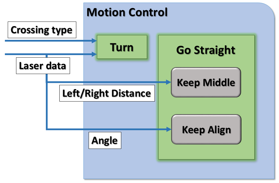
Compare left and right distance, combined with P controller to make the PICO in the middle of corridor; Check the angle of the PICO.
Turning
- Detect range:-20°-80°,20°-80°
- Check the differences between the sensor return values
- Oval trace
- Memory the corner for DP
Map Saving
Door Detection
Presentations
- First presentation (week 3): File:First presentation.pdf
First presentation is about: Task-skill-motion system architecture and the composition pattern.
- Second presentation (week 6): File:Second presentation.pdf
Second presentation is more about: Coding and Composition Pattern.
- Final presentation (week 8): File:Final presentation 11.pdf
Maze Competition
Function Description
Front Road Detected
The different kind of front roads will be set as different flags. The robot will base on those flags to determine the next action to handle the cross.
Take into account the left, right and straight way, the all the situation the robot will meet is:2^3=8
Put all the situation into flags as
| Left | Right | Straight | Flag |
|---|---|---|---|
| Open | Open | Open | 1 |
| Open | Open | Open | 2 |
| Open | Open | Open | 3 |
| Open | Open | Open | 4 |
| Open | Open | Open | 5 |
| Open | Open | Open | 6 |
| Open | Open | Open | None(keep going) |
| Open | Open | Open | 7(Dead-end) |
Result and Evaluation
The evaluation of the maze competition: What went well? what went wrong? why? how could it be improved?
