Embedded Motion Control 2014 Group 3
Group Members
| Name: | Student id: |
| Jan Romme | 0755197 |
| Freek Ramp | 0663262 |
| Anne Krus | 0734280 |
| Kushagra | 0873174 |
| Roel Smallegoor | 0753385 |
| Janno Lunenburg - Tutor | - |
Time survey
Link: time survey group 3
Planning
Week 1 (28/4 - 4/5)
Finish the tutorials
Week 2 (5/5 - 11/5)
-
Software
Overview
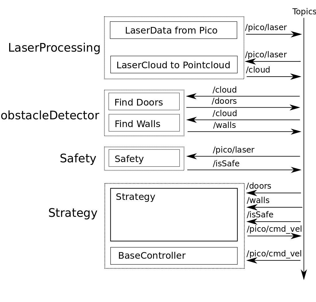
In the overview the different packages (dotted boxes) and nodes (solid boxes) are displayed. The topics are displayed at the sides of the nodes.
LaserProcessing
LaserData from Pico
The data from the laser on pico is in lasercloud format. This means that the data is represented in an array of distances. The starting angle and angle increment are known. This means we have the distances from laser to objects for a range of angles.
LaserCloud to Pointcloud
Because we are going to fit lines to the walls, it would be easier to have tha data in Carthesian Coordinates. In this node the laserData is transformed in a PointCloud, which is published on the topic. It is also possible to filter the data in this node when needed. For now all data is transformed into the PointCloud.
Safety
The safety node is created for testing. When something goes wrong and Pico is about to hit the wall the safety node will publish a Bool to tell the strategy it is not safe anymore. When the code is working well safety shouldn't be needed anymore.
Obstacle Detection
Select Walls
In FindWalls lines are fitted over all the walls. In selectwalls the walls are filtered to find the two walls in the driving direction. The walls are send as a starting and endpoint. To be able to compare the walls to eachother, the begin point is projected on x=0 (at height of Pico). The closest walls left and right of Pico with the same direction are the two walls to use for navigation.
Next part should be in strategy i think
From the grade of the walls compared to Pico a setpoint can be set on a certain distance in x direction, on which pico can correct to drive straight. A setpoint further away leads to smaller corrections compared to a setpoint closer to pico. The setpoint can also be uses for taking the turns.
Notes (TODO)
+ Pointcloud X,Y
+ Fit lines
+ Remove negative X points
+ Select closest and parallel in X direction lines (one with Y>0 one with Y<0), the left en right wall
+ Y of waypoint = Yw = average slope of parallel lines * 1m
- ang.z = sign(Yw)*Yw^2*tunefactor
- If 2 parallel walls can be found, drive in X direction
- No walls? Crossing.
