Embedded Motion Control 2014 Group 10: Difference between revisions
No edit summary |
|||
| Line 52: | Line 52: | ||
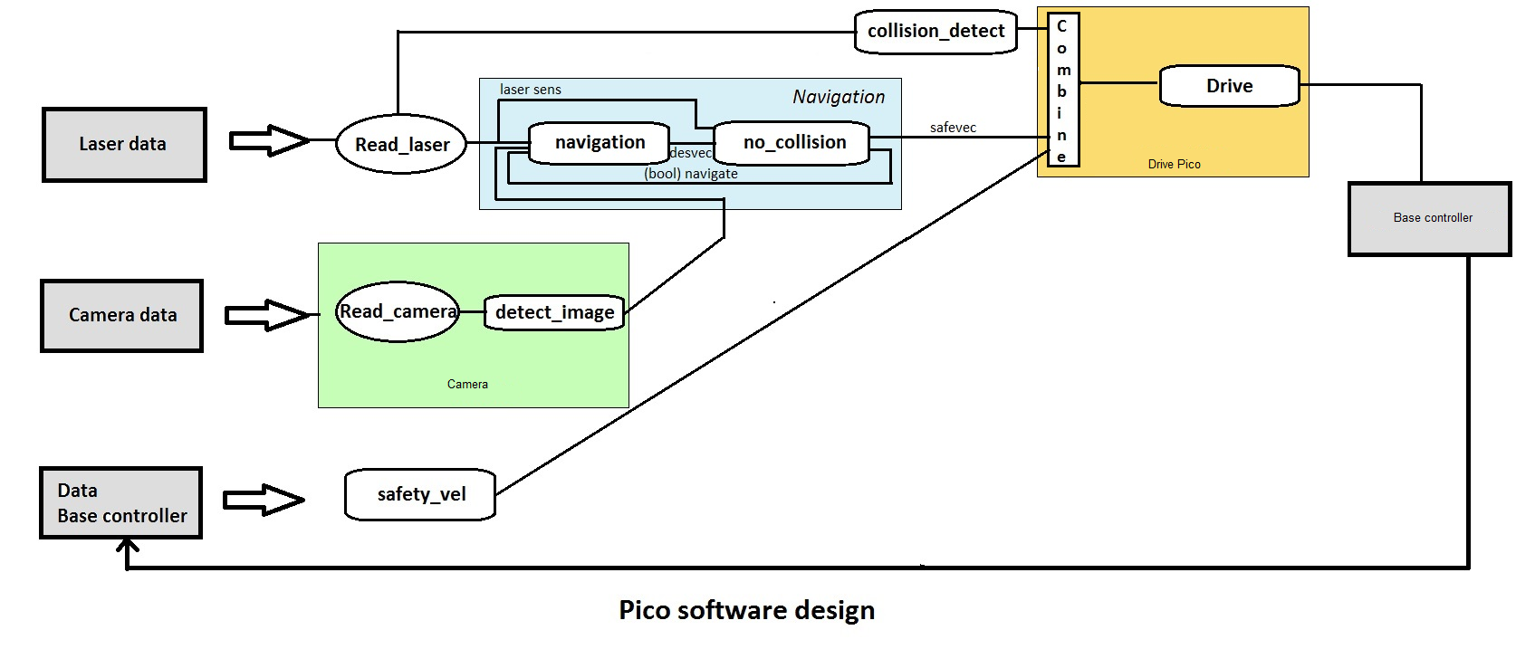
[[File:Pico_software_design.png|1200px]] | [[File:Pico_software_design.png|1200px]] | ||
''' | '''Wall detector''' | ||
The wall detector determines whether the robot is close to a wall or not by determining the unblocked distances at its two sides. When either side is too close (within 30cm) it turns parallel to that side, taking a distance of 30cm from the wall. | The wall detector determines whether the robot is close to a wall or not by determining the unblocked distances at its two sides. When either side is too close (within 30cm) it turns parallel to that side, taking a distance of 30cm from the wall. | ||
| Line 59: | Line 59: | ||
[[File:pico_detect_intersect.png]] | |||
'''Intersection detection''' | |||
''' | |||
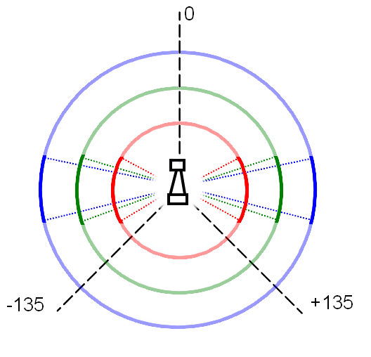
When driving forward, Pico uses the measured distances at different angles from the laser data in order to detect corridors. These distances are visualized in the figure on the left. The red circle part covers 72 degree with a radius of 0.5m, the green circle part covers 35 degree with a radius of 1.0m and the blue circle part covers 25 degree and a distance of 1.5m. The circle part tips outside of pico are on two parallel lines 60cm apart. When each of this circle parts doesn't detect any obstacles inside, this is considered to be the corridor. | When driving forward, Pico uses the measured distances at different angles from the laser data in order to detect corridors. These distances are visualized in the figure on the left. The red circle part covers 72 degree with a radius of 0.5m, the green circle part covers 35 degree with a radius of 1.0m and the blue circle part covers 25 degree and a distance of 1.5m. The circle part tips outside of pico are on two parallel lines 60cm apart. When each of this circle parts doesn't detect any obstacles inside, this is considered to be the corridor. | ||
| Line 69: | Line 66: | ||
All holes smaller than 0.30m will never be detected as corridor because the slimmest part of the laser range bundle outside pico is 0.30m. (Just outside the part covered by the red circle part, inside the blue circle part). The smallest hole that always will be determined as corridor is 0.60m; the laser covers a with of 0.6m. Holes within 0.30m and 0.60m might be determined as corridor, dependent on the length of the exit and pico's positioning. | All holes smaller than 0.30m will never be detected as corridor because the slimmest part of the laser range bundle outside pico is 0.30m. (Just outside the part covered by the red circle part, inside the blue circle part). The smallest hole that always will be determined as corridor is 0.60m; the laser covers a with of 0.6m. Holes within 0.30m and 0.60m might be determined as corridor, dependent on the length of the exit and pico's positioning. | ||
|} | |} | ||
'''Intersection determination''' | |||
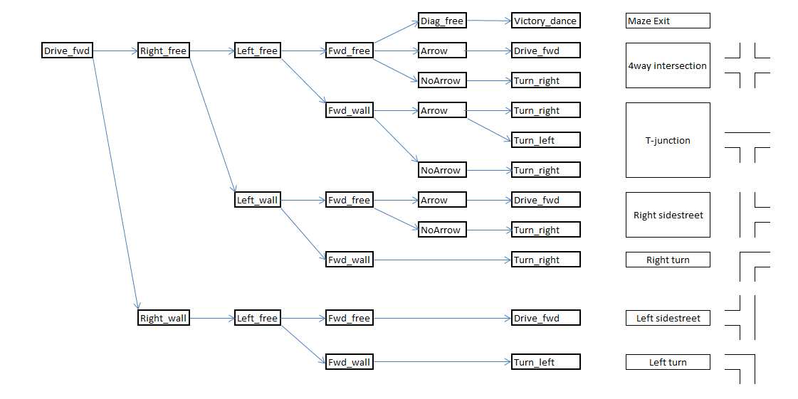
Depending on the results from the intersection detection part, Pico will determine which situation he is in. In the maze, these situations could be 4-way intersection, corners and T-junctions. The image below shows how each situation is determined depending on the presence of a wall or corridor in the forward, left or right detectors. | |||
[[File:navigation_protocol.jpg]] | |||
Revision as of 11:41, 26 May 2014
Members of group 10
| Bas Houben | 0651942 |
| Marouschka Majoor | 0660462 |
| Eric de Mooij | 0734166 |
| Nico de Mooij | 0716343 |
Planning
Week 1
- Introduction
- Install Ubuntu
Week 2
- Determine the course goals
- Brainstorm about the robot control architecture
- Start with the tutorials
Week 3
- Continue with the tutorials
- Install ROS/QT
- Finish robot control architecture
- Brainstorm about collision principle
- Brainstorm about navigation
Week 4
- Meet with the tutor
- Finish installation
- Finish tutorials
- Write collision detection
- Write corridor navigation
- Test the written code on Pico
- Corridor challenge (Recorded performance)
Concepts
Robot program architecture
The idea of our architecture is to create different process layers. By splitting the incoming signals and combining them later, the tasks can be divided and the different processes can run in parallel. Layers are based on the available sensors as much as possible.

Wall detector
The wall detector determines whether the robot is close to a wall or not by determining the unblocked distances at its two sides. When either side is too close (within 30cm) it turns parallel to that side, taking a distance of 30cm from the wall.
When driving forward, Pico uses the measured distances at different angles from the laser data in order to detect corridors. These distances are visualized in the figure on the left. The red circle part covers 72 degree with a radius of 0.5m, the green circle part covers 35 degree with a radius of 1.0m and the blue circle part covers 25 degree and a distance of 1.5m. The circle part tips outside of pico are on two parallel lines 60cm apart. When each of this circle parts doesn't detect any obstacles inside, this is considered to be the corridor.
All holes smaller than 0.30m will never be detected as corridor because the slimmest part of the laser range bundle outside pico is 0.30m. (Just outside the part covered by the red circle part, inside the blue circle part). The smallest hole that always will be determined as corridor is 0.60m; the laser covers a with of 0.6m. Holes within 0.30m and 0.60m might be determined as corridor, dependent on the length of the exit and pico's positioning.
|}
Intersection determination
Depending on the results from the intersection detection part, Pico will determine which situation he is in. In the maze, these situations could be 4-way intersection, corners and T-junctions. The image below shows how each situation is determined depending on the presence of a wall or corridor in the forward, left or right detectors.

