Embedded Motion Control 2013 Group 8: Difference between revisions
| Line 152: | Line 152: | ||
'''''Input messages''''' From Drive controller node: messageCloseToGap[bool closeToGapLeft, bool closeToGapRight] | '''''Input messages''''' From Drive controller node: messageCloseToGap[bool closeToGapLeft, bool closeToGapRight] | ||
'''''Output messages''''' messageDriveNode[int toDoMotor] (toDoMotor is turnLeft, turnRight, driveStraight and maybe sligthlyLeft, slightlyRight) | '''''Output messages''''' messageDriveNode[int toDoMotor] (toDoMotor is turnLeft, turnRight, driveStraight and maybe sligthlyLeft, slightlyRight) | ||
Since standard ROS messages do not include a boolean, it is easier to use the std_msgs::Float32MultiArray. | |||
====pseude Code==== | ====pseude Code==== | ||
Revision as of 11:23, 4 October 2013
Group members
| Name: | Student id: | Email: |
| Robert Berkvens | s106255 | r.j.m.berkvens@student.tue.nl |
| Jorie Teunissen | s102861 | j.a.m.teunissen@student.tue.nl |
| Martin Tetteroo | s081356 | m.tetteroo@student.tue.nl |
| Rob Verhaart | s080654 | r.a.verhaart@student.tue.nl |
Tutor
| Name: | Email: |
| Rob Janssen | r.j.m.janssen@.tue.nl |
Minutes
Planning
Week 1 (02-09-2013 - 08-09-2013)
- Installing software
- Following tutorials
- Setup SVN
Week 2 (09-09-2013 - 15-09-2013)
- Installing Jazz simulator
- Brainstorm on functions
- Setting up plan of approach
- Martin: Measure middle road driving
Week 3 (16-09-2013 - 22-09-2013)
Week 4 (23-09-2013 - 27-09-2013)
- September 25th Corridor Challenge
Week 5 (30-09-2013 - 04-10-2013)
Week 6 (07-10-2013 - 11-10-2013)
Week 7 (14-10-2013 - 18-10-2013)
Week 8 (21-10-2013 - 25-10-2013)
- October 23th Final Challenge
Strategy
Modules:
- Route calculation node
- Corridor detection
- Relative location in corridor
- map
- route calculation
- motor controller
- Drive node
- Arrow node
- Drive controller node
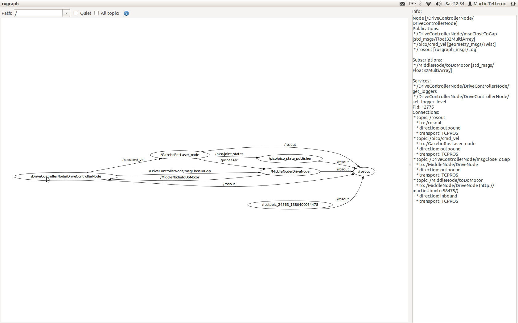
A diagram of the node communication File:Node communication.pdf
Route Calculation Node
The goal of this node is to solve the maze. It keeps track of the previous movements of the robot and calculates the route to solve the maze. The following modules are defined on this node.
Output message to drive_controller: MessageRoute[float DistanceToDrive, int toDoMotor], where todomotor is turnRight, Turnleft or DriveStraight
Corridor detection
This function detects all the walls. The walls are outputted as line segments in x,y coordinates.
Input: Laser_vector[1081] output: Vector[Lines], with lines[float x_begin; float y_begin; float x_end; float y_end]
Relative location
This function calculates the distance from the wall on the left and on the right and the angle of the robot towards these walls.
Input: Laser_vector[1081], Vector[Lines] Output: Location_rel[ float Dist_left; float dist_right, float Theta]
If the shortest distance to a wall is not the laser data directly right or left, pico is not parallel to the wall. The angle can be calculated by taking the difference of the shortest laser angle and 90 degrees.
Map
Using the results of the previous modules this module will update the current map. The location of the robot and the walls/corners/deadends will be drawn in the map. The starting point of the map (0,0) is the start point of the robot. So every time the map from this point will be calculated. As an improvement a particle filter might be needed to draw a better map.
Input: Vector[Lines], Location_rel Output: Location_abs[ float x, float y, float theta] Global: Map[vector[Lines], locations_visited[x,y]]
Route Calculation
This module calculates the route to the next goal. If the goal is in a different corridor and multiple small steps are needed to drive to this goal, a reachable setpoint is calculated and the goal is saved.
Input: Location_abs, location_rel, Map Output: Location_goal[float x, float y], Location_setpoint[float x, float y] Global: Location_goal[float x, float y]
Motor Instruction
This module translates the calculated route and the current location to a message to the motor. The motor commands are turnLeft, turnRight, driveStraight. The module outputs a message to the drive controller node
Input: Location_setpoint[float x, float y], location_rel[float x, float y] Output: float distanceToDrive, int toDoMotor (left, right, driveStraight are defined as integers)
Drive Node
This node makes sure that pico keeps on driving in the middle of a corridor, so it is not crashing into one of the walls. The node can receive an input message from the Drive Controller Node about the distance to a gap in the walls. If Pico is close to a gap, the function is not trying to drive in the middle of the corridor, but parrallel to the wall without the gap. The node outputs messages to the Drive Controller Node with the information about how to remain in the middle of the corridor. This node updates faster than the Route Calculation Node.
Input messages From Drive controller node: messageCloseToGap[bool closeToGapLeft, bool closeToGapRight] Output messages messageDriveNode[int toDoMotor] (toDoMotor is turnLeft, turnRight, driveStraight and maybe sligthlyLeft, slightlyRight)
Since standard ROS messages do not include a boolean, it is easier to use the std_msgs::Float32MultiArray.
pseude Code
if(middleDrive)
- Drive in the middle of the corridor (if not close to a gap)
elseif(parrallelLeft
- If a gap is on the right side of Pico, start driving parrallel to the left wall. The location of a gap is send by the Drive Controller Node using messageCloseToGap
elseif(parallelRight)
- Same as left, but now the gap is on the left.
elseif(turnLeft)
- If in the middle of a gap, start making the turn to the left or right
elseif(turnRight)
- Same as above, but now turn right
Arrow Node
This node is optional, if we have enough time we will try to implement this node. This nodes uses the camera information to detect arrows. If an arrow with a direction is detected, a message will be sent to the drive controller node were to drive to.
Output Messages MessageArrow[bool turnLeft]
Drive Controller Node
This node is the node which decides which commands are send to the motor. This function is on it's own node, because it has to listen to the calculated route and to the middledrive. The calulcation of the route calulcation is needed less frequent than the middledrive check. If
Input messages: MessageRoute[float DistanceToDrive, int toDoMotor], messageDriveNode[int toDoMotor], MessageArrow[bool turnLeft]. Output Messages messageCloseToGap[bool closeToGapLeft, bool closeToGapRight]
Algorithm
Gapdetection
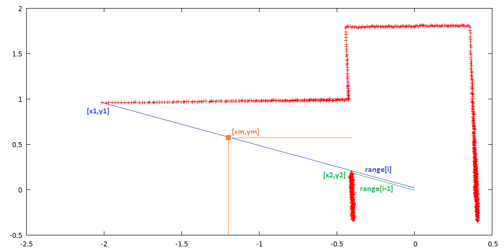
Input: Laser_vector[1081] output: gap location [float x1; float x2; float xm; float y1; float y2; float ym]
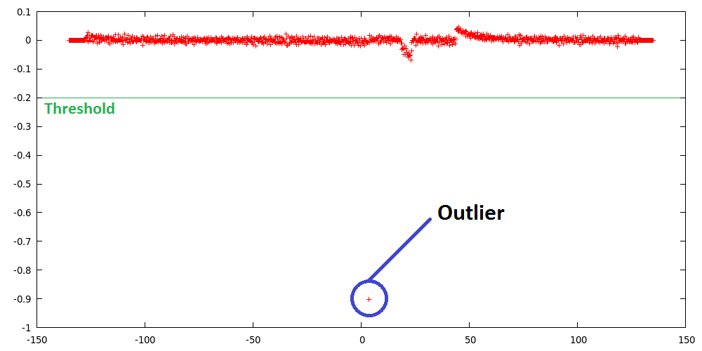
A gap is detected by thresholding the derivative of the laser ranges, this derivative is defined as the difference of laser range [i] and [i-1]. If this difference is larger than the threshold, laser range [i] and [i-1] are labeled as gap corners. The function then starts calculating the position of these laser reflection points relative to its own position. The corner closest to the robot is labeled as point1 [x1,y1] and the other as point2 [x2,y2], the function also outputs the euclidean middle of both points [xm,ym].
Simulation results
Experimentation results
Corridor detection
We failed to succeed the corridor comptetition. We were given two opportunities to detect a hole and drive though it. However, the first attempt the safety overruled the state machine that was build, and the robot got stuck. the second attempt the robot didn't turn far enough and Pico was unable to correct the angle correctly, after which it again got stuck in the safety mode.
First Attempt
When the robot was started, the MiddleDrive function worked properly and Pico started of nicely. Whenever the robot drove towards a wall, the MiddleDrive corrected for it and made sure that the robot drives straight forward. However, when the robot approached the corner whithin 0.5 meter range, it seemed like the robot corrected to drive exactly to the middle of the hole. Since your workspace is rather small and SafeDrive defines a space of 40 cm around every angle of the robot, the robot approached the was too close and the SafeDrve overruled the normal behavior of the robot. So the robot tried to correct for the hole, but instead drove too close too the wall and got stuck in the SafeDrive mode.
Second Attempt
The second attempt the robot started of nicely again, driving straigt forward. When the robot approached the hole on the left within the range of 0.5 meters, it slowed down. Pico corrected a bit to the right, but stopped nicely in the middle of the hole. However, when the turn was started, it seemed to approach a wall again, such that the SafeDrive took over again. We confirmed that the turn was never completed and the robot got stuck agan in its safety mode.
Conclusion
Unfortunately, we didn't succeed the corridor competition, but we learned from our mistakes and know how to approach the problem correctly. Next time we'll have to make sure to reserve more time with the robot to learn its behavior in practical situations. All in all, we have to make sure that the safety doesn't overrule the normal behavior of the robot too soon.


