Embedded Motion Control 2012 Group 2: Difference between revisions
No edit summary |
|||
| Line 116: | Line 116: | ||
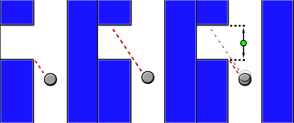
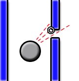
In order to make the software robust against holes in the wall or things like this, a small fan of laser points is used. While testing the robot detected a corner at a location where this really wasn’t possible, the reason turned out to be a small gap between the plates of the maze. So instead of basing the corner detection and path centering algorithms on a single point of the laser array, a number of points are now used. For the algorithms that determine the corner detection and the centering of the robot in the corridor, specific angles in the array of laser data points are used. Around this angle, we now use a series of points and determine the minimum of this series. This point is then used as before as the distance at that angle. In the picture below, this is the marked point. | In order to make the software robust against holes in the wall or things like this, a small fan of laser points is used. While testing the robot detected a corner at a location where this really wasn’t possible, the reason turned out to be a small gap between the plates of the maze. So instead of basing the corner detection and path centering algorithms on a single point of the laser array, a number of points are now used. For the algorithms that determine the corner detection and the centering of the robot in the corridor, specific angles in the array of laser data points are used. Around this angle, we now use a series of points and determine the minimum of this series. This point is then used as before as the distance at that angle. In the picture below, this is the marked point. | ||
The series will consist of 15 points for a specific angle, which for a total of 1081 data points around 270 degrees, comes down to a fan of about 3 degrees. So when the corridor has a diameter of 1m, the robot can handle a gap of up to about 3cm. | The series will consist of 15 points for a specific angle, which for a total of 1081 data points around 270 degrees, comes down to a fan of about 3 degrees. So when the corridor has a diameter of 1m, the robot can handle a gap of up to about 3cm. | ||
<br/> | |||
[[File:gap detection.jpg]] | |||
<br/> | |||
==Arrow detection== | ==Arrow detection== | ||
Revision as of 15:53, 31 May 2012
Group Members
| Name | ID number | |
|---|---|---|
| T.H.A. Dautzenberg | 0657673 | T.H.A. Dautzenberg |
| V.J.M. Holten | 0655090 | V.J.M. Holten |
| D.H.J.M. v.d. Hoogen | 0662522 | D.H.J.M. v.d. Hoogen |
| B. Sleegers | 0658013 | B. Sleegers |
| Mail to all |
Tutor: Janno Lunenburg
Project Progress
Week 1
- Installation of Ubuntu, ROS and Eclipse
- C++ tutorial
Week 2
- ROS tutorial
- Meeting 1 with tutor
- Read Chapter 1 and 4 of Real-Time Concepts for Embedded Systems
- Made a presentation of Ch. 4 for lecture 2 [Slides]
- Prepared the lecture about Ch. 4
Week 3
- ROS tutorials continued
- Looking up useful information and possible packages on the ros website
- Formulating an idea to tackle the problem
- Trying to run and create new packages but running into some problems
- Presented Ch. 4
- Extra research regarding the API and Linux scheduler, as requested by Molengraft
Week 4
- Created a node which makes sure Jazz doesn't collide with the walls
- Created a node which enables Jazz to make the first left corner
- Research on different maze solving algorithm's
- Presented extra research regarding the API and the Linux scheduler briefly
Week 5
- Trying to create the path detection and autonomously cornering
- Made a start regarding arrow detection (strategy follows)
Week 6
- Further work on arrow detection
- Created a program with which we are able to accomplish the corridor competition
- First test with Jazz, Thursday 13:00 - 14:00
Components Needed
- Wall detection
- Laser scan data: Done!
- Arrow detection
- Camera data
- Path detection (openings in wall and possible driving directions)
- Laser scan data
Mapping (record traveled route and note crossroads)(we will probably not use this anymore)- Control center (handels data provided by nodes above and determines the commands sent to the Jazz robot)
Strategy
- use the laser pointing forward to detect dead-ends, then turn 180 degrees.
- use lasers pointing left & right to keep the robot in the middle of the path.
- use lasers pointing 45 degrees left and right to detect corners. If there is a 'jump' in the data, there is a corner. The new and old laserdata are then used to create a setpoint in the middle of the corner to which it will drive. It will then turn left/right 90 degrees and start driving again until it detects a new corner.
- we will probably use the right turn algorithm.
- use 2 nodes. One for the camera (which is only partly done) and the other node for the rest (corner detection, decision making, etc.). This is because the arrow detection should run at a much lower frequency due to the large amount of data.
Path detection and corner setpoint creation

Robustness in laser detection
In order to make the software robust against holes in the wall or things like this, a small fan of laser points is used. While testing the robot detected a corner at a location where this really wasn’t possible, the reason turned out to be a small gap between the plates of the maze. So instead of basing the corner detection and path centering algorithms on a single point of the laser array, a number of points are now used. For the algorithms that determine the corner detection and the centering of the robot in the corridor, specific angles in the array of laser data points are used. Around this angle, we now use a series of points and determine the minimum of this series. This point is then used as before as the distance at that angle. In the picture below, this is the marked point. The series will consist of 15 points for a specific angle, which for a total of 1081 data points around 270 degrees, comes down to a fan of about 3 degrees. So when the corridor has a diameter of 1m, the robot can handle a gap of up to about 3cm.
Arrow detection
Arrow recognition

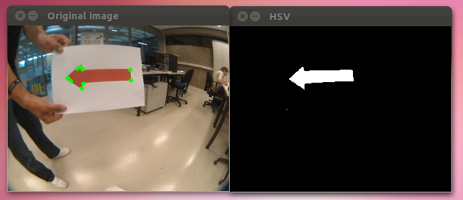
Left the original image with detected green dots, right the HSV thresholded image. We still have to figure out how to convert these green dots to whether or not the arrow is pointing left or right.
(we're also using the 2.x API (cv::Mat) instead of OpenCV 1.x API (CvArr))
First test with Pico (31/05)
The test turned out very well. We first had to rewrite some things in order to take the larger laser data array into account (1081 points instead of a lot less). But when this was fixed our first test immediately had the hoped result. The corner was detected and the robot drove through the corner properly without bumping into any walls. A link in the movies section was added where the result of a test is shown.
Movies
Corner competition test: Corridor_test_1
