PRE2019 4 Group9
Group members
| Name | Student ID | Department |
|---|---|---|
| Pim Claessen | 0993712 | Applied Physics |
| Bengt Frielinck | 1269593 | Automotive |
| Matthijs Marinus | 1000921 | Software Science |
| Max Opperman | 1232427 | Computer Science and Engineering |
| Thomas Willems | 1022753 | Software Science |
Final video
Problem Statement
From the beginning of mankind some 2 million years ago, humans have never lived in a more connected, safe world. People can travel the world by plane and car and we have a system to protect and help us from danger and misfortune. However, this is the modern way of life that has not completely eliminated all dangers. Due to our connected world death by road accident is a common occurrence definitely under younger ages[1]. In these accidents, people can get stuck inside or under a car. The current tools used to free these people are hydraulic pumps, spreaders and cutters[2]. While these can effectively help free people they also take quite some time to set up and use, time that is not always there. This is why we propose the use of an actively powered exoskeleton. Firetrucks can be equipped with this exoskeleton and firemen can put it on while driving to the emergency. This will provide instant superhuman strength for any situation. In the case of a person being stuck under a car, the car can be lifted the moment the firemen arrive and valuable minutes are saved that are normally needed to set up a hydraulic jack. Firemen are only 1 example of the emergency workers benefiting from the superhuman strength given by an active exoskeleton. The flexible design we propose can improve rescue workers' effectiveness in all areas, for example, disaster areas, where lifting rouble and carrying people all day puts a heavy strain on workers' bodies. In this report, a concept design for such a flexible, multipurpose, active exoskeleton will be given
User Group
We will be designing our exoskeleton for use by emergency responders. In most situations, these will be firefighters. However, we will keep other use cases in mind for example for police officers or search and rescue operations. Firefighters have an incredibly difficult and dangerous job. Typical firefighter emergency scenarios include medical emergencies, vehicle accidents, building collapse, and of course putting out fires among others. These are difficult, strenuous activities often carried out in very adversarial conditions. It is then not surprising that one of the major causes of death for firefighters is overexertion, being struck by objects or getting caught/trapped [3][4]. Our exoskeleton should help alleviate this group by reducing the number of physical exertion firefighters have to undergo while performing our jobs. We also hope the exoskeleton can provide the firefighters with the extra boost in strength to free themselves or people they are helping in dangerous situations. The exoskeleton should also serve as a type of shield by taking some of the blows of various objects hitting the firemen since the exoskeleton will cover a large part of their bodies. It will also help them carry people much easier out of dangerous situations, or move heavy objects trapping people. You could also think about tall buildings which are on fire. Firemen have to carry equipment up a large set of stairs. Currently, there is already an exoskeleton design that helps firemen carry up to 40kg of weight making this task much easier and faster [5]. It should also be applicable in traffic accidents where victims are stuck in folded cars. Often firemen are called in these scenarios to cut open the car. This is a difficult process and having an exoskeleton to bend or break critical parts should be a tremendous help.
Another great user groups are search and rescue workers. After a natural disaster, these people are deployed to find and help people who are in danger. This usually involves freeing people from under a large pile of debris from collapsed buildings or other items. These operations usually take a long time and a lot of equipment. [6] Shows a company that has developed an exoskeleton already for this case allowing the user to have extra power to move debris or objects for a long period under harsh conditions. These are definitely some of the features we want to equip or exoskeleton with.
Police officers could also benefit from using this type of technology. As explained in [7] police officers often have to carry heavy equipment like gun vests or gun belts with them. This coupled with long-standing hours causes a lot of police offers to eventually develop health problems in their back or legs causing them to become unemployed. If they were to carry and exoskeleton during long work hours we could alleviate some of this repetitive strain.
User research
Fire Department Interview 1
We are trying to contact our local fire- and police departments to interview some people about exoskeletons and how they would use this technology. For the first interview, the Brandweer Eindhoven Centrum Eindhoven (040-2203203) was contacted who forwarded our call to a fireman at the station. We asked him the following questions after which we will write a summarized answer to the conversation:
1. Do you know of any exoskeleton suits currently in use or development at any fire station in the Netherlands?
As far as he was aware, the use of this particular technology was not in use anywhere. He had only seen it use in medical applications thus far.
2. Do you see any use and/or necessity for an exoskeleton?
In his honest opinion not really, at least not for the work he carried out. We informed him of some of the death report numbers of firemen usually dying from over-exhaustion or getting stuck in dangerous situations. He however did not share these concerns and in his opinion, it would not be really necessary.
3. Could you think of any situation where an exoskeleton might be practical?
The only situation where he thinks it might be helpful is extinguishing fires over longer periods since this can be quite exhausting but further than that, for the work he carried out he still felt like it would be unnecessary.
4. What are your biggest concerns about the use of this technology?
The main issue he saw, and mainly why he would not really see the benefit of this technology is that in his opinion it would take too long to get into. In high-pressure situations, every second is of essence which they train a lot and his perception of exoskeletons was that they take a really long time to get into. Time, that in his opinion, you do not really have. Furthermore, he thought that something that covered most of your body would be too bothersome to use. He gave the example of climbing a fence for example for which you need quite a lot of flexibility or when you are walking through a house you do not want to keep bumping into objects.
5. What are your main requirements if you would use this technology?
His main requirements followed by the previous question. If he had to use it he would not want it to hinder him in his movements and it should also be very easy to get in and out of.
Fire Department Interview 2
Through some private contacts, we were able to arrange an interview with William Elseman, a volunteer fireman. I started the interview by introducing William to the subject of exoskeletons and our plans to design one for use by the fire department. I also told him some of our ideas for the design, e.g. being used for carrying rubble/people or assisting with long hosing times.
1. Do you know of any exoskeleton suits currently in use or development at any fire station in the Netherlands?
“No, I have never heard of this technology being used by any fire department.”
2. Would you want to use this kind of technology? What do you think of the uses we propose?
“Well, the most important thing to understand is that our biggest concern is always our own safety. You do not enter a building if you are not sure you can get out and when we arrive at the scene with six people, we leave with six people. Because of this carrying rubble would never be a good application for an exoskeleton. Once a building has burned down so far that it starts collapsing, we will not enter. Instead, we would probably have a crane or a ‘Bobcat’ (a brand of crane vehicle) to move the rubble. I do agree that it can be very useful in carrying people out of buildings though, as it can be quite a challenge to carry, well… ‘larger’ people out of a building. Normally when we enter a building the most restricting factor is the amount of oxygen in our tanks. The more effort something takes (e.g. hosing a fire or heavy lifting), the more oxygen we use, resulting in less time we can spend inside the building. If an exoskeleton would reduce some of these efforts, it could greatly extend the time we could be active inside a building.”
3. Could you think of another situation where an exoskeleton might be practical?
“A lot of other jobs we do is what is called “Technische Hulpverlening” (THV). This is needed at heavy car crashes for example. When we need to break open a car or cut two cars apart, etc., we use hydraulic equipment. These hydraulic shears are very heavy and can sometimes require two people to operate. I think an exoskeleton might be a perfect application for this type of situation. Another thing I can think of is when we are dealing with large house fires we often deploy a water cannon, which is incredibly heavy. Again, being able to carry such heavy equipment by yourself would help a lot.”
4. Are there any last concerns you have for such an exoskeleton?
“First of all, keep in mind that when dealing with fires, we already have heavy gear on our backs, namely our oxygen tanks. There is not much room for battery packs or any other equipment or electronics. Secondly, make sure the fireman operating the exoskeleton is still able to reach his communications device and that none of the electronics interfere with the signal. Communication is very important when dealing with these dangerous, high-pressure situations.”
I ended the interview by thanking William for his time, after which he suggested he could try to get me in contact with one of his superiors at the volunteer fire department. We got confirmation we can contact this next user and intend to conduct an extra interview to ask further about the specific requirements for an exoskeleton used for THV.
Police Department Interview 1
After a bit of emailing back and forth, we were also able to get an interview at the Eindhoven police department. Officer Gijs Craenmehr had read our e-mail and was so excited he invited one of us over to the station to do the interview and to look at some police cars to think about transport for the exoskeleton.
We first talked about the current state of the art within the police force, and just as with the fire department, no such thing as exoskeleton technology is being used yet. Gijs did point out that in the next couple of years the police uniform is going to get a complete technological revamp, so hopefully, they would see some glimpses of this tech in the upcoming years.
Thereafter Gijs showed me around all the police vehicles they use, most of which are also used by the fire department, just with a different paint job. The most interesting vehicles to us are the vans they use, specifically the Volkswagen Transporter modified for bicycle transport. This kind of modification resembles what would be needed for our exoskeleton the most. The van seemed just right for the job, big enough for a mobile exoskeleton team, but would also be able to store enough other equipment in the back.
Lastly, we were joined by Gijs’ colleague Joost and we talked about exoskeleton needs within the police force. Their most common strenuous work is having to stand a long time, while also having to carry at least 10 kg of gear with them at all times. They showed me some of the different tools, equipment, and bulletproof vests they have to carry with them and I quickly understood why this could lead to back and shoulder problems. Being able to spread out the strain and the effort of this work would be the biggest improvement for their jobs. We ended up concluding that although the current scope of our design is not large enough to encompass the use for police as well, the heart of the problem they would want to be solved, is basically the same; it is not a lack of power to do something, but rather they want a reduction of the effort it takes to do something over an extended period of time. Whether it is carrying hydraulic equipment for a few minutes or just standing for hours on end, help with those tasks seems greatly more appreciated and necessary than being able to lift a car with superhuman strength.
We also briefly touched on fully weaponized, “Iron Man”-esque exoskeletons, and although all three of our sci-fi hearts longed for something like that, we quickly came to the realization that it would just not be as useful as a simple skeleton that would help with every day strains. And of course, the Dutch government would never use something like a weaponized exosuit in the foreseeable future, not in the police force anyway, but probably not in the specialist forces either.
I thanked Gijs and Joost for their time and enthusiasm to discuss our designs with them, and they let me know that I could always contact them if we have any further questions.
Use Case Scenarios
After conducting the interviews we decided that the best use case for our exoskeleton would be supported in “Technische Hulpverlening”. To have a clear understanding of the function of our design and the scope of the project, we have described 2 scenarios that portray the usage of our exoskeleton. Disclaimer: John the firefighter, our exoskeleton specialist in these scenarios, is purely fictional. These scenarios and his handling in them however is based on the results of our user research and our interviews with real first-aid responders.
Scenario 1
At 13:51 a call arrives at the fire station. A car has hit a tree and the driver is unresponsive. The door is stuck and they cannot get to the passenger. It had been fairly quiet at the station all morning, but by 13:53, just two minutes after receiving the call, everyone is suited up and ready to go. Among them is John, who will be handling the hydraulic equipment today, although most of his suit awaits him in their transport vehicle. John and his three colleagues get in the right van and before the clock strikes 13:54 they are on the road.
The back of this van is specifically modified to house a special piece of equipment, a hydraulic exoskeleton sat on a special seat on one side of the van. As soon as they got in the van, John sat in that seat and started strapping his legs into the exoskeleton. He knows he has approximately 5 minutes to strap in, so he makes sure works precise and everything is secure and in place. He then sits up straight and the one colleague that is in the back of the van with him helps him strap in his arms and upper body. After checking everything one last time, John’s colleague can prepare the rest of the equipment, while John just has to wait until they arrive.
By 14:00 they arrive at the scene, 6 minutes after leaving the station. The two firefighters in the front seat start approaching the crashed vehicle and setting up blockades on the road. John gets out of the van with the help of his colleague, and they both start setting up the hydraulic tank and equipment they will need. The person in the vehicle is still unresponsive and he is stuck, so the other two firefighters start stabilizing the car with blocks and they carefully pop the windows so they do not break while cutting out the door. In the meantime, all of John’s equipment has been secured and checked properly, and he has gotten clear to approach the vehicle and start.
John engages his exoskeleton and walks up to the front of the car, the suit making the equipment feel not much heavier than actual scissors. He gauges where he will need to place the first cut, making sure not to hit dangerous parts like the suspensions, and then he cuts just above the wheel. The next cut goes with the same speed, ease, and precision and before you know it the first two cuts are done. John then asks his colleague, who had been standing by at the ready, to hand him the other pair of hydraulic scissors. After the quick equipment change, John makes the final cut, and two of his colleagues carry out the door. The medical personnel that has since arrived quickly take the person out of the vehicle and John and his crew start decoupling his equipment. He gets back into his seat in the van and straps out of his exoskeleton, locking it in the seat while he and his team deal with the aftermath of this incident.
Scenario 2
At 6:30 in the morning, there had been a call about a fire at one of the industrial areas right outside town. The department quickly found out this fire was a lot bigger than it had seemed at first and after sending out two full extinguishing teams, at 6:42 the department decided to send John with the exoskeleton, along with another extinguishing team. Just like every time John straps into the exoskeleton as soon as he gets in the van. His colleague helps him secure his upper body and arms, and because they have a bit of a long drive to the scene, they discuss their course of action when they arrive. Their colleagues have already been at the scene for about 10 minutes and have described the fire, so they can already plan out where they want to place the water cannons vaguely.
When they arrive, John gets out of the van immediately and he and his colleague quickly set up his hydraulic tank. Then John walks over to the firetruck of the extinguishing team that parked right alongside them, engages the exoskeleton, and takes out the two water cannons from the back of the truck. He also grabs the necessary hoses and walks over to their previously designated spot with one of the cannons. He places the cannon where he thinks would be the best exact spot and one of his colleagues connects all the hoses and starts the cannon. John easily makes some final adjustments for the aim of the high power cannon, aiming it at the flaming roofs of the factory. He then walks back to the other cannon and repeats this exact same process for it as well.
Once he finishes setting up the second cannon, the fire has already greatly diminished, largely thanks to John’s quick set up of the cannons, but also because of the three brave extinguishing teams doing their jobs excellently of course. All that is left to do is adjust one of the cannons one more time and then the extinguishing teams can clean up the smallest flames.
With the fire mostly extinguished and the water cannons no longer needed, John and his colleague decouple them, and John carries them back to the firetruck. They store everything neatly, decouple the hydraulics from John’s exoskeleton and then John gets back in the seat in the back of the van. Once John has strapped out of the exoskeleton he and his colleague get in the front of the van and leave the scene. Their driver on their way over to the scene had been part of the extinguishing crew and will join them in their truck on the way back. The exoskeleton has done its job for this incident and needs to be returned safely to the station.
Use Case
From both the user interviews and the scenario's the use case can be created. This mostly includes decreasing the effort of carrying heavy equipment like hydraulic shears. From the interviews, we learned that for really high-pressure scenarios like rescuing people from burning houses, an exoskeleton would first of all not really be necessary, as told to us by the first fireman we interviewed, and also that putting on the exoskeleton would probably cost too much valuable time. Instead, we moved to support carrying heavy equipment as William Elseman suggested. The goal of our exoskeleton is that working with heavy equipment can both be done by one man (wearing the exoskeleton) instead of two or more and also that this will take much less effort decreasing the risk of injuries from accidents by not being able to handle the equipment properly because of its weight and long term injuries from working with heavy equipment for long periods of time.
When conducting THV, firefighters do not use oxygen tanks and thus have no equipment on their backs, giving us a lot more freedom in design and making it a lot more feasible to be able to get in and out of the exoskeleton quickly. In THV firefighters also do not experience extreme heats like in house fires, so our concerns for extreme heat resistance can be put aside.
From the user research, we can make the following list of user requirements which we will reference in the system requirements such that our requirements are relevant to user needs.
- [UR01] - The exoskeleton shall not hinder the user in their required movements
- [UR01.a] - The exoskeleton shall not restrict easy access to the communications device of the fireman
The needs for this requirement was clearly expressed by the first interviewed fireman. One of his main objections to using an exoskeleton would be that he feared that the exoskeleton would hinder him while carrying out movements that required a higher degree of agility. Not taking this requirement into account would certainly result in our exoskeleton being unusable in practice. Extra attention in regards to the movement of the exoskeleton must be paid to sub-requirement a, as mentioned by William.
- [UR02] The exoskeleton shall be easy to get into.
Another critical factor that the fireman expressed which would turn him off to the idea of using an exoskeleton would be the time it would take to get into one. When firemen get sent out for an emergency every minute is of the essence and if the exoskeleton takes too long to get into, then in all reality it would not really be usable. Technical assistance scenarios are usually not immediate life or death so it does not have to be seconds however also not more than a few minutes.
- [UR03] The exoskeleton will make the user able to lift heavy equipment by himself without straining effort.
This requirement shall have the benefit that one man instead of two is needed for jobs thereby decreasing the number of firemen required and also caters to our goal of reducing the amount of effort it takes to carry out these tasks.
State of the Art
The main approach that will be used is to combine different innovations from all kinds of different types of exoskeletons. From different parts of the body to different types of exoskeletons (varying goals). [8] shows that currently, a problem many exoskeletons face is the tradeoff between rigidness and agility. Often a more rigid skeleton can provide more stability/force but in practice is quite cumbersome. The exoskeleton in [5] is an example of an exoskeleton designed for firemen. It provides support for the back and shoulders and is a good example of something we would like to achieve, alleviate some of the heavy work. [9] Discusses some positive/negatives of a back support exoskeleton mostly used in the treatment of SCI (spinal cord injury). The interesting part of this article is that it also discusses some of the dangers involved in using an exoskeleton like bone fractures and skin shearing. Furthermore, it also discusses how tailor-made most exoskeletons are and that most take a lot of practice to get used to. The last problem it brings up is that they also take a lot of time to get into. These are all problems we are going to have to think about in our project. Article [10] shows the relevancy of this topic. It talks about a so-called AFA exoskeleton which is currently being developed specifically for firemen. It should give a fireman the ability to carry loads up to 100kg while in only weighs 23 kg itself where most of the weight is being transferred to the floor. One of its main uses is that you can replace 2-3 firemen, which is typically needed to hold and control the motion of a firehose, by 1 fireman who can operate and move it all by itself.
[7] Talks about the impact exoskeletons could have on police work. A lot of injuries over the long term are caused by repetitive strain from carrying gun belts, bullet-resistant vests, and long periods of standing. As is the case for firemen, who also carry a lot of gear and are likely to have to stand for long periods of time, our ES should alleviate this repetitive strain keeping the emergency responders in better health for a longer time. [6] Displays another great possible use case exoskeletons, some of which we want to replicate in our model. It involves an exoskeleton designed for dangerous and heavy search and rescue work under extreme conditions. It allows the user to carry heavy objects with greater ease and for longer periods of time helping with moving debris or heavy objects. This is also a functionality we want to have.
There have also been other previous attempts to assist firefighters. D. Sasaki & M. Takaiwa wrote a paper[11] about a pneumatic power assist wear to relieve some of the physical burdens that firefighters experience by heavy equipment as, for example, a heatproof suit. Even though this not really the same as an exoskeleton it is still a powered device to support firefighters with their heavy work. We might derive some of the features that were presented by D. Sasaki & M.Takaiwa in our exoskeleton. Pneumatics is in the very core principle the similar to hydraulics, which makes use of liquids instead of gases. Something that is well designed in this powered assist wear is that it does not limit the degrees of freedom of the user. This effect is achieved by letting the device being made of cloth. The result of this research is that when the user equips heavy equipment to the upper body, the device can reduce the muscular burden of the user's knees and waist.
In 2018 M. Bolignari et al. published a paper on the design and experimental characterization of a hydrostatic transmission for upper limb exoskeletons[12]. The paper starts to point out that in general, exoskeletons that employ electric motors as actuators. However, this causes problems with the inertia of the moving parts because of the weight of the actuators. This can be solved by delocalizing the motors from the parts that need to move with a high velocity. However, this leads to higher complexity, and assembly and maintenance can often only be performed by highly instructed personnel. Hydraulics and pneumatic systems on the other side, are generally more difficult to be controlled. The main reasons for this are the pressure-regulation system and the complexity of striction forces, which is the friction that is obstructing stationary parts from moving. Elastic components can smooth out this problem and ensure safe interaction with the user. Bolignari et al. proceed to present a joint with one degree of freedom that is controlled by a fluid transmission system of both a hydraulic - and pneumatic line as well as electrical motors. This combines the benefits of the electric motors and the specific power of the fluid actuation. This combination is then presented in an upper limb rehabilitation exoskeleton. The shoulder has three degrees of freedom, the robotic joint with the hydrostatic transmission is only applied in one of the degrees of freedom. This means that the arm is assisted when lifting in front (or behind, even though this is less likely) of the user. When lifting the arm to the side or twisting the arm, the exoskeleton moves with the user but the actuation system does not enhance the movement. The paper concludes with the fact that the exoskeleton is a promising development due to the operational costs and potentially moderate manufacturing.


A book has been written on the design, control, and applications of exoskeletons [15]. There are a few things this book highlights with regards to currently design challenges of exoskeletons:
- Portability
- Ease of use
- Metabolic cost
- Lightweight actuators
- Actuators that can supply high torque at slow speeds
- Actuators that are soft and flexible
- Intuitive control systems
- Control systems that adapt to the changing dynamics of the human
Metabolic cost is an important factor since most exoskeletons are so heavy that they actually increase the metabolic cost of moving with the exoskeleton on, which defeats the purpose (usually, depends on the goal of the exoskeleton) in most cases. We do not look at the changing dynamics of the human since we will not be focusing on people from different age groups. Ease of use and portability are probably of most significant to us since we expressed these in the user requirements. The writer predicts that the device weight will be reduced in the future by developing better actuation techniques and using smaller batteries. Chapter 5 brings forth research and discusses challenges with arguable the most complex part of an upper-body exoskeleton which is the shoulder. The shoulder joint is one of the more complex joints in the human body with arguable 5 degrees of freedom. This is why it is one of the hardest joints to model. A big problem with most current designs that use three revolute joints to simulate spherical motion is that they often collide with the user's body because of their size and orientation on the shoulder. There the book offers its own design which is a double parallelogram joint. Using this type of joint they were able to achieve The shoulder joint is able to realize approx. 120 shoulder abduction, 110 degrees shoulder internal rotation and 30 of external rotation. This was deemed enough because most carrying activities take place in front of the body instead of near the sides of the body.
This[13] article discusses the design of an elbow exoskeleton. An important note brought forth by the article is that the “physical human-robot interaction” (the area where the exoskeleton actuates the joints) should be large and follow the shape of the human limb. This should reduce the pressure on the skin of the user. The design is then explained, first they show a double “shelled” structure as displayed in the figure 1 below. The goal of this structure is to reduce the pressure on the skin of the user. Most exoskeletons use bar-shaped structures however this design is usually cumbersome and reduces inertia and kinematic compatibility with the limb. This is an interesting design decision which might also be helpful in the prospective model project. Furthermore, the article introduces a design for a 4 DOF elbow mechanism which takes into account the variability of the motion of an elbow. The elbow is actually not a firm axis (does not move in a straight line) but has an elliptical cross-section. The design proposed by this article deals with this problem by adding extra joints within the mechanism which allow more 3-dimensional motion while also supporting actuation of the standard axis of motion of the elbow (flexion and extension).
[14]Presents an interesting design of the shoulder joint. This is one of the harder joints to model since it contains a lot of different ranges of motion, therefore it is difficult to align the joints of the exoskeleton which the joints of the human. The article presents a system consisting of 3 serial revolute joints which together act as a ball and socket joint like our shoulder. There are placed in such a way that their center of rotation aligns with the users center of rotation of the shoulder. An example of this design can be seen in the figure below.
Requirements
Within the design of an exoskeleton, multiple required features should be present, depending on the user of the exoskeleton. Keeping in mind that the users of the exoskeleton will be emergency services we came up with the following requirements respecting the requirements ISO 29148 for systems (and software) engineering. Note that these requirements can be altered in a later stage if we find them to be unreachable for our system. Some of these requirements are linked to user requirements which are specific to cater to the needs of users, others are requirements we felt would be most beneficial to a practical and useful exoskeleton to be used in real life. Some technical requirements (e.g. about materials, the support mechanism, and forces) can be found below. The exoskeleton should also fit an average-sized firefighter, which we chose to be a male. This choice is based on the fact that only 6 percent of the Dutch firefighters are female[16]. According to the Dutch Central Statistics Office (CBS, from the Dutch “Centraal Bureau voor de Statistiek”), 42 percent of men have a length that differs less than 5 centimeters from the average of 1.81 meters[17]. Therefore we want our exoskeleton to be somewhat flexible in size such that it can differ from the average height. Our exoskeleton will not have attributes to support the head of the user thus it will be approximately 10.75% less[18], which is equal to approximately 0.195 meters thus the exoskeleton will be approximately 1.615 meters high. However, the space above the shoulders might be used if we deem it necessary e.g. for the support of the back or shoulders of the user but only till the height of 1.81 meters. The average depth of a male is 30 cm and the average width is 60cm[19]. Besides the sizes, our exoskeleton also has to be ‘safe’. Since this requirement is too complex to fully cover, we will simply say that there should always be an opportunity for the user to easily get out of the exoskeleton or move away from danger while still inside the exoskeleton. The latter could be by e.g. loosening all the hinges and pivoting points such that the user can freely move.
Transportation
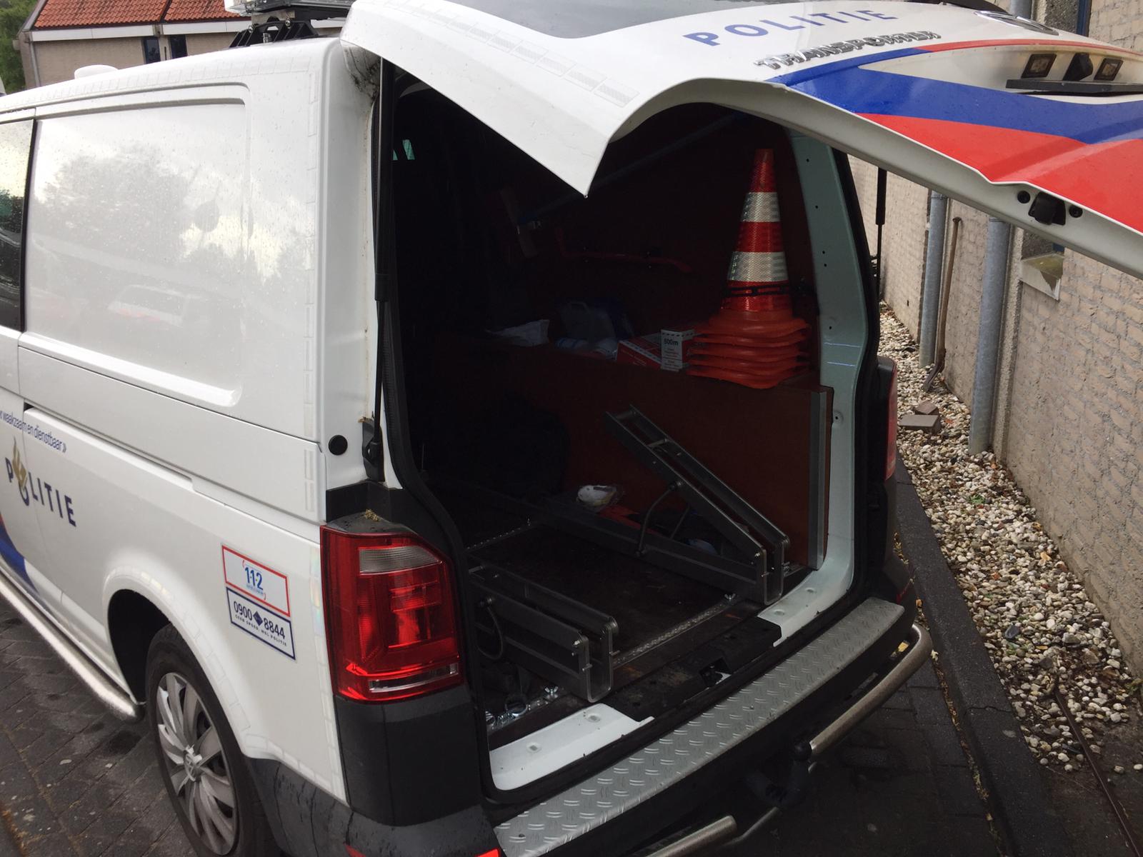
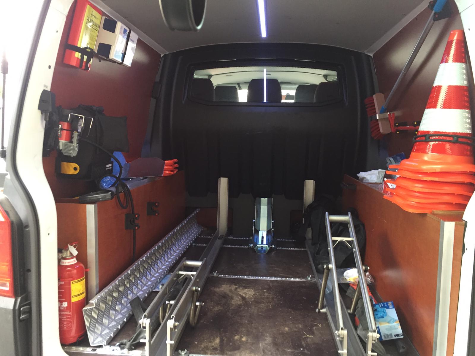
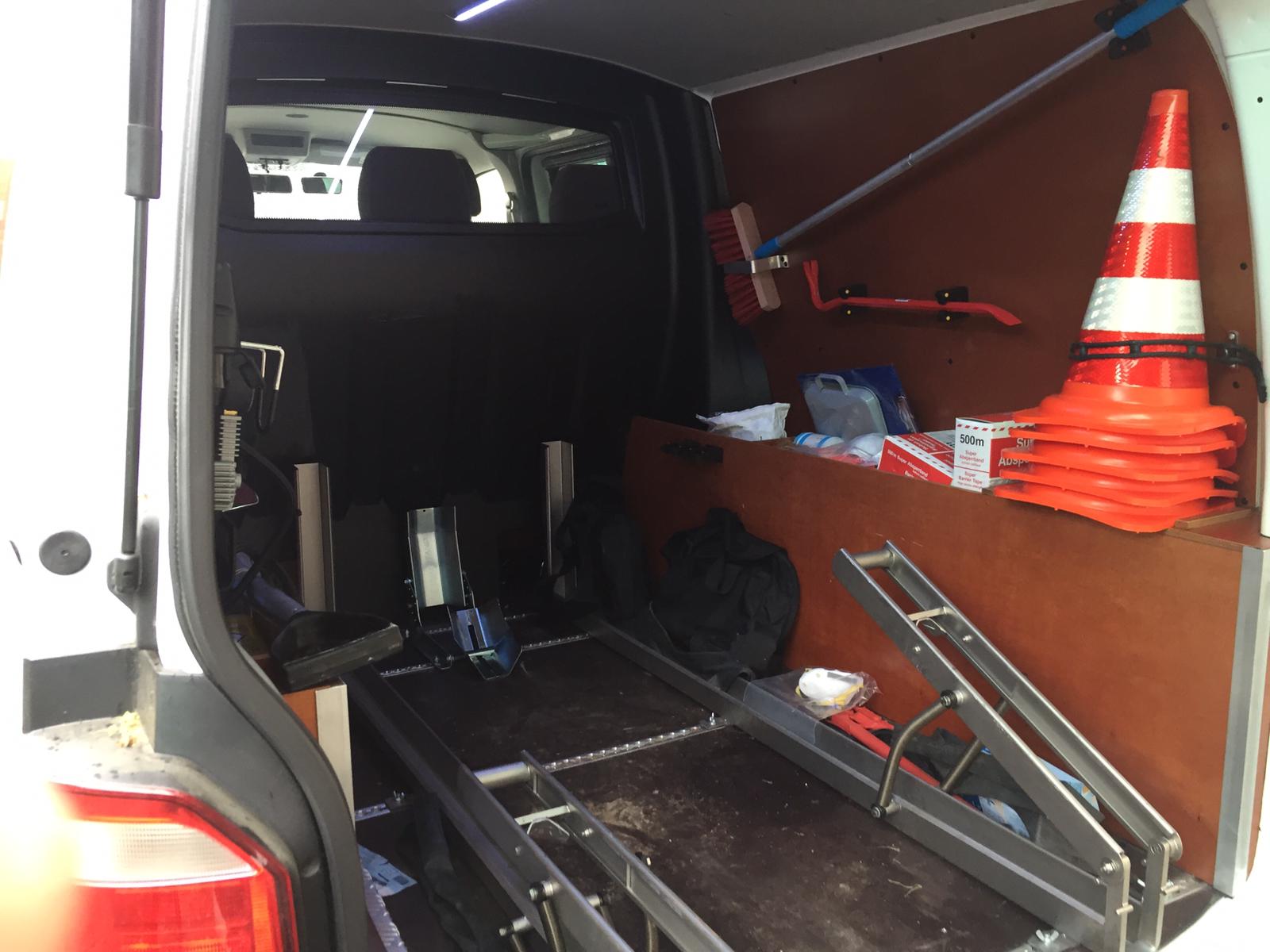
- The exoskeleton shall fit the trunk of a Volkswagen Transporter van.
- - For our user research we visited the police. Even though our use case is not specifically applicable to policemen, we still acquired some useful information. For example in the transport, as can be seen in the pictures below. The police make use of a Volkswagen Transporter van, which the fire brigade also utilizes[20]. The dimensions of the trunk of the van are 230x145x140 (LxWxH), in cm[21]. Note that the space is not high enough for the exoskeleton to stand upright in since it must fit a fireman who has a medium build. The most viable option will be to lay down the exoskeleton on the ground or to let it sit. The latter of these options could make it more comfortable for somebody to wear it during transport. Also, this guarantees that other people in the trunk can more easily move around. This might help when the user wants to put on the exoskeleton on the way to the incident. However, these are both not prerequisites so sitting and laying down suffice.
- Volkswagen Transporter used by the police
Outside view with the trunk lid
Inside view
Inside view slightly angled


Movement Requirement
We do not want the users to be burdened or restricted during movement as explained in UR01. This is true for normal movements like walking as well as straining movements like lifting. To achieve this the model needs to mimic the natural degrees of freedom (DOFs) of the human body. We can split the body up into two parts (upper and lower body) for which we can study the DOF individually.
Studies [22][23] find that there are 7 relevant degrees of freedom in the human arm. Three in the shoulder, one in the elbow and three in the wrist. For our project, we will not have to worry about the wrist since the exoskeleton will only provide support here, which will not restrict the movement of the user. There are thus 4 degrees of freedom to account for. There are three DOFs in your shoulder called the shoulder yaw, pitch, and roll as shown in figure 3.

Humans also have one DOF (slight axial rotation takes place while flexing or extending your elbow, however, these are not necessarily required for the movement [25]) for the elbow which is the elbow pitch as shown in figure 4. With these four degrees, you can basically move your arm in any direction you want, any movement is a combination of these four DOF as displayed in studies like[26][27]. We need to incorporate at least some degrees for each of these DOFs to support most of the movement needed by firemen. The tools that the firemen normally use which we are focusing on (jaws of life, firehoses) are normally carried near the waist and are usually never lifted above the shoulder. This means that the shoulder roll and shoulder pitch should be able to reach 100 degrees if you take holding your arm straight in front of you to be the 90-degree angle. The shoulder yaw is not really relevant for the movements necessary but since we will probably model our shoulder joint in three DOF we will take it into account anyway. For the elbow pitch it would be usefull to support full extension and contraction of the elbow [28] so from a straight 0-degree angle to a 140-degree angle, we will not incorporate the 10-degree hyperextension which humans are capable of since this is unneccesary for normal movement and only brings safety issues regarding overextension. These ranges of motion should allow the user to at least move the tools in the angles and positions necessary to carry out their tasks.

Robotic legs are often modeled with 6 or 7 degrees of freedom as shown in [29] [30]. At least three are required for walking in a straight line[30] however we will focus on six (two in the ankle, one in the knee and three in the hip) since this will give us a wider degree of movement. The relevant degrees are shown in the figure 5. For the most parts when handling the tools the fireman will stand up straight, however, we want to support kneeling as well. This means that we have try to support a 0 degree to 120 degrees [28] (fully contracted) range of motion for the DOF in the knee as well as a hip pitch of 200 degrees (to be able to put a leg behind your body) to 30 degrees when lifting your leg upwards. Furthermore, we also want to be able to put the legs to the side which is the hip roll of at least +40 and -40 degrees starting from a 180-degree straight leg[28]. We also need to support +30 and -30 degrees of hip yaw motion to be able to move your legs towards our outward of your body[28].

Time Requirement
The person shall be able to get into the exoskeleton within 4 minutes. [UR02] The exoskeleton will be transported in a van in which the designated person will have the put on the exoskeleton. This means that he has to be able to put on the exoskeleton in the time it takes to respond to calls. First, we researched the average response times of Dutch firefighter departments. Statistics[32] indicate that the average response time for fire departments in the Netherlands was (219.7 minutes /26 departments) = 8.45 minutes. However the user can only put on the exoskeleton while being driven to the destination, thus we will have to look at the average time it takes to drive to the destination. The average driving time is (110.2 minutes/26 departments) = 4.24 minutes [32]. We, therefore, feel that 4 minutes is adequate time. This will likely require that other persons traveling to the destination will have to help with putting on the suit. Firemen are luckily already very trained in putting on gear so we feel like this is an attainable goal. We will keep this in mind when designing the exoskeleton, making it in such a way that it will not be overly complicated to put on.
Support Mechanism
- The exoskeleton shall carry at least its weight. [UR01]
The exoskeleton should not put extra weight on the user when standing still. This means that the exoskeleton can stand on its own and the user will only have to carry parts of the exoskeleton when moving. For example, when moving the right arm, the user will only feel like they are carrying the arm due to the force needed to move the exoskeleton from one position to another. Once the arm is in position and is kept still, the exoskeleton shall support itself again and no carry weight is felt by the user.
To be able to do this the exoskeleton must be able to deliver a constant force to support itself and whatever the user is carrying. There are a few options to take into consideration for the support mechanism, namely hydraulics and electric motors. The most logical option to do this is with hydraulics. Hydraulics are already being used in a lot of current exoskeleton projects. They offer the required DOF and could easily support its own weight and the equipment being used. The heavy life support gear being used, such as the hydraulic shears, already require an external hydraulic tank that can support multiple devices. Not having to carry its own tank makes the exoskeleton significantly more flexible and lighter, while also ensuring the hydraulics will be able to provide the required power as mentioned above. The other option, electric motors, seems a lot more inconvenient for our use case, as it would need a lot of complicated circuits and sensors and it would need to carry its own very large battery. This technology could be used to design our exoskeleton, but Ockham's razor suggests hydraulics to be the far better option for our design.
Material Requirement
- The exoskeleton shall resist heat radiation up to 4.6J/(s*m2) for a maximum of 180 seconds.
- - Firefighters outfit are meant for heat radiation from 1.0 kW/m2 up until 4.6 kW/m2. However, activities at 3.0 kW/m2 may only last 3 minutes to not cause pain. At this intensity of the radiation heat, build-up forms a risk after 20 minutes. Activities at a maximum of 4.6 kW/m2 must last less than 3 minutes. After this period a safe area must be reached.[33] This is a regulation from the Dutch National Expertise Center Fire Brigade Decisions on Major Accident Risks (Dutch: “Landelijk Expertisecentrum Brandweer Besluit Risico’s Zware Ongevallen”). Trivially, the exoskeleton may not be less resistant to heat than the firefighter's outfit.
- Taking into account the 3 minutes that were mentioned before: 4.6 kW/m2 * 180s = 4600 J/(s*m2) * 180s = 828 000 J/m2.
- A standing person who is skiing has the frontal area of 0.61m2[34]. However, taking into account the firefighter's outfit we will assume that the frontal area is 1m2. This gives us 828000J as a maximum which leads to 435.9958833142289 Celsius Heat Units. This means that after approximately 436 CHU the material should not melt. We assume the starting temperature to be 20°C.
- Note that this requirement has been chosen to make the exoskeleton more future-proof. By giving the exoskeleton this requirement, it is possible that the exoskeleton might also be used in situations where heat and fire play a role. Again, this requirement is based on the heat resistance of outfits of firefighters, which is the above mentioned 4.6J/(s*m2) for 180 seconds.
Here we will justify the choice we made regarding the material. We have to took into account the previous statements about weight and heat resistance. In addition to this, we also have to take into account the strength of the material. It has to be a solid material that is quite stiff. The following materials were found with these properties:
| Material | Tensile Yield Strength | Compressive Yield Strength | Density | Hardness (Brinell, Knoob, Rockwell C, Vickers) | Rigidity | Melting Point | Further Notes |
|---|---|---|---|---|---|---|---|
| Titanium Grade 6 | 827 MPa | 830 MPa | 4480 kg/m³ | 320, 363, 36, 349 | 48.2 GPa | <= 1590 °C. However, 2.80 MPa at temperature 540 °C with time >= 3.60e+6 sec | 517 MPa Tensile Strength at temperature 427°C [35] |
| Titanium Beta C | 825 MPa | - | 4820 kg/m³ | 304, 330, 32, 318 | - | 1555 - 1650 °C | Due to Wikipedia indicating that this material has the tensile strength of 1400 MPa we researched this material. However, we found that it was incorrect.[36] |
| Titanium Grade 5 Annealed at 700-785°C | 880 MPa | 970 MPa | 4430 kg/m³ | 334, 363, 36, 349 | 42.1 GPa | 1604 - 1660 °C. However, 150 MPa at temperature 455 °C during >=360000 sec | Tensile Strength is 620 MPa at 427°C[37] |
| Titanium Grade 5 Solution Treated 900-955°C, Aged 540°C | 1100 MPa | 1070 MPa | 4430 kg/m³ | 379, 414, 41, 396 | - | 1604 - 1660 °C. However, 210 MPa at temperature 455 °C during >=23400 sec | This has been treated at a slightly higher temperature than the above, resulting in recrystallization (as explained here[38]).[39] |
| Carbon Fiber Reinforced Carbon Composite (CFC) (Light) | 68.9 MPa | 172 MPa* | 1650 kg/m³ | - | - | 400 °C | * We use the value for compressive strength on a plane of CFC for this.[40] |
| Carbon Fiber Reinforced Carbon Composite (CFC) | 103 MPa | 200 MPa* | 1750 kg/m³ | - | - | 400 °C | * We use the value for compressive strength on a plane of CFC for this.[41] |
Note: we also looked at grades below grade 5 for titanium. However, we quickly found out that the density is higher for those than for titanium grade 5, hence they are not mentioned here.
The most viable materials that were researched is Titanium Grade 5, either the annealed or tempered variant. The version we choose depends on the ease with which we can import both variants in Fusion 360. We have a slight preference for the version that has been treated at a higher temperature. Since Fusion already had a preset for the Annealed version of Titanium Grade 5 (Ti-6Al-4V), this material will be used. This material is relatively lightweight, stiff, and especially strong such that it can support the user. It also is relatively heat resistant, though as mentioned before, it loses some strength at high temperatures.
Force requirement
In this section, the forces on different parts of the exoskeleton are calculated. The forces are calculated for an exoskeleton designed for a sturdy human male while carrying the hydraulic equipment. In the calculations, the weight used for the hydraulic equipment is set at 20kg. This is the heaviest the equipment may be according to EU laws governing the safety of firemen.[2]. The weight for the firefighter is taken at 85kg and standard proportions are assumed.
Shoulder joint
Standard weight and length proportions are found using ExRx body segment data.[42] 5.7% of the weight is in the arms. 3.25% in the upper arms, 1.87% in the lower arms, and 0.65% in the hands. Using the male weight of 85kg the total weight of 1 arm is then 0.057*0.5*85=2.42kg. The upper arm, lower arm, and hand are in order 17.2, 15.7, and 5.75 percent of the total height of an average male. The ratio between these parts is 2.99 : 2.73 : 1. In the figures below this is the ratio between A : B : C. To calculate the force on the shoulder the torque formula should be used which states that the torque on an object is equal to the force perpendicularly multiplied by the distance. (This means that for the force calculations to give a correct value at all different angles the force and the arm of the force must be perpendicular introducing a sin or cos function. It is however not necessary to calculate this for different angles and taking the sin and cos into calculation since we only need to look at the maximum force the joint should be able to hold, which is when the force and the arm are perpendicular.) Rewriting the torque formula for the shoulder joint of the exoskeleton gives the formula below:
F_sup=d_ac*F_(work) / d_afsup
Where F_sup is the supporting force, which is the force that the shoulder joint needs to deliver to keep the weight elevated, d_ac is the distance from point A to C, F_work is the force gravity exerts on the hydraulic equipment and d_afsup is the distance between point A and the attachment point of F_sup.
To keep a stretched arm in place horizontally using the lengths above with the supportive brace mounted exactly in the middle between A and B gives the relation: F_sup=3.83 F_work This means that holding up 20 kg with a stretched arm requires a supportive force of 3.83*(20+2.42)=85.87 Kg. This is the maximum weight the shoulder joint of the exoskeleton should be able to support.
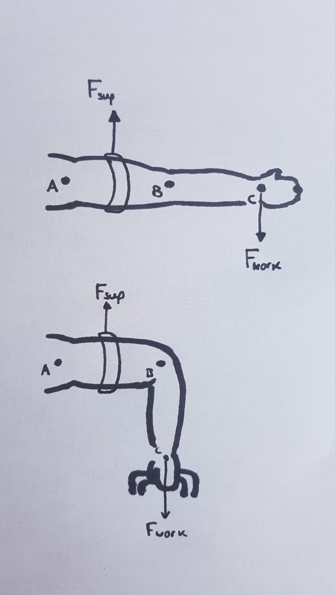
Figure 5: Forces on arm joint
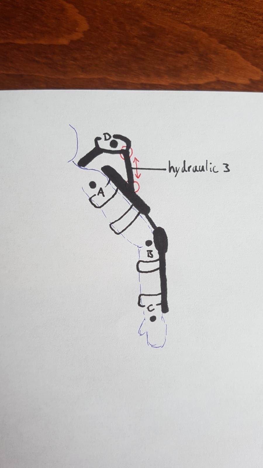
Figure 6: Forces on shoulder joint


Elbow joint
The hydraulics of the exoskeleton should be able to hold equipment of 20kg at the wrist with a bent arm. For the average man, the length of the wrist to elbow is 0.157 times his height. The average dutch male has a height of 182cm and thus the length from the wrist to the elbow will be around 28.57cm. This length is visually represented by the distance from B to C in the figure below. The other important arm is that of the supporting force of the cylinder to the pivoting point. In the figure, this is represented as the distance from point B to the attachment point of the hydraulic cylinder (red circle). It can be easily seen that the maximum this distance can be equals to the radius of the circle around which is 5cm. To calculate the force these 2 cylinders must absorb we can use the following formula:
F_supp=d_bc*F_work / d_bfsupp
Where F_supp is the maximum force the joint should hold, d_bc the distance between points B and C, F_work the force gravity exerts on the hydraulic equipment in hand and d_bf1 the distance between point B and the attachment point of force F_supp. For 20kg weight, this means that the 2 cylinders together must absorb a maximum of 28.57*(20+2.14)/5=126.50 Kg (1241 N)

Knee and hip joint
The exoskeleton should support its own weight plus what the person is holding, in this case, equipment of 20kg. The exoskeleton itself weights 40 kg. While walking the magnitude of the force on the leg varies throughout the movement. For the exoskeleton’s structural integrity the only number that counts however is the maximum force the exoskeleton has to endure at any point. This force can be calculated by taking the change in momentum over the change in time, in formula form this reads:
F=m*dv/dt
Plotting this for the walk of a person gives the following graph:

This gives that the maximum force a leg while walking is ~1.25 times our body weight. This means the exoskeleton has to be able to endure at least (40+20)*1.25=75 Kg of force per leg.
Design
General design


The exoskeleton was modeled in Autofusion 360 which is a 3D modelling platform. It has many capabilities such as stress testing and collaborative working tools. It also has a large library of components and materials which will be useful to get the most accurate real-life simulation of our model. A key part of our design is the ability to pick the specified Titanium Grade 5 (Ti-6Al-4V) as the material for the model. This ensures that the simulations will be calculating with the actual properties of this material. The properties of this material in Autofusion are shown in figure x. Figure x shows the current properties of the model with relation to area, density, mass and volume. Furthermore it is important to keep in mind that this is only a concept model which will focus on proving the movement and force requirements specified earlier. This in combination with our limited experience in CAD will mean that the model will be fairly basic. The model, as most projects do in real-life, will likely need some more design iterations to make it a fully functioning, good-looking exoskeleton.
In the model you will be able to see straps on different parts of the exoskeleton. These straps are mostly an indication on where on the body these straps should be and is open to a more advanced design. Currently they are modeled as flexible rubber straps but could also be modeled as velcro straps or straps made of a different sturdy material with some kind of locking mechanism similar to backpack straps/locks for example. The most important part of these straps is that they create a tight connection between the human body and the exoskeleton such that the loads are properly distributed and the user actually receives support from the exoskeleton.
A fairly important part that we have not yet covered so far is the control system used for controlling the exoskeleton. The exoskeleton should move in synchrony with the user, applying force whenever the user is straining and relieving force whenever the user’s muscles relax again. We have chosen to omit this part since we could not really modell it anyway and there are also a lot of different control strategies documented in other studies. Important is that the control strategy is safe and accurate. It should not make extreme increases in applying force and should be able to pick up on small movements to allow the exoskeleton to mode in synchrony with the user. Chapter 5.5 of the book Wearable Exoskeleton Systems - Design, Control and Applications talks about approaches to different control strategies and control algorithms [15] and could be a source of inspiration for viable options for our exoskeleton regarding limb control.
Lower body design
This section will cover the design of the lower body section of the exoskeleton. Figure 12 shows an overview of the leg. Visible are the hip joint, upper leg, knee joint, lower leg, ankle joint, feet and the hydraulics which will power the leg. The most important function of the lower body design is to meet the requirements set in the movement requirements section. As such most time was spent on making joints which have the required degrees of freedom. Currently 4 out of the 6 required degrees of freedom are modelled due to CAD constraints however we will provide sources with examples of fully modeled joints which could be used for a final design.

Upper/Lower Leg
The upper and lower leg are comprised of two titanium bars connected to joints on various ends. These joints are made from the titanium alloy chosen. They are scaled in relation to the height chosen for the exoskeleton. In practice it would follow some iterative design phases to see which lengths are most comfortable/fit best. Attached to the back of these parts are the hydraulics which drive the legs. These will be covered later. Both to the upper and lower legs also have straps which connect the users legs to the exoskeleton.
Knee joint
The knee joint was modeled as a simple cylindrical joint. As specified by the movement requirement it only needs to have 1 degree of freedom. The knee in motion can be seen in animation 1. The leg can be moved from a 0 degree straight angle to a contraction of 120 degrees powered by the hydraulics. However, the complexity of the design was kept minimal and in practice, a more advanced and stylized joint can be modeled. Examples of knee joints that can further expound on the complexity of the design can be found in article[44]. Here the joint is based on a very accurate biomechanical model such that the joint is placed precisely on the center of rotation the human knee joint which is key to prevent injuries and/or discomfort when using an exoskeleton. It also has a similar circular design. [44] Also follows a design similar to the one modeled for the project, where the hydraulics are replaced with a spring mechanism. However, the fundamentals of the knee joint remain the same. The model, therefore, proves that the basic concepts implemented within the design can work when used in practice.

Ankle joint/feet
The main purpose of this section of the model is to provide contact with the ground such that the load can be distributed to the ground. As such we kept this part of the model simple only show a 1 degree of freedom joint for the ankle and a strap which goes underneath the shoe which connects the exoskeleton to the ground and thus distributes the load. As such this part of the model was kept simple, only showing a 1 degree of freedom joint for the ankle and a strap that goes underneath the shoe which connects the exoskeleton to the ground and thus distributes the load. A design we have in mind of this part is something like the Suit X exoskeleton [45] where the ankle joint is more flexible and less bulky.
Hip
The hip joint currently incorporates two degrees of freedom, one for the hip pitch (lower part) and one for the hip roll (upper part). Modeling 3 degrees if very difficult in CAD, therefore, we limited it to these two for our model which should be enough for a basic movement like crouching, walking and standing.[46] shows a hip joint which is modeled for all the degrees of motion which uses an “axis translation” system of the hip yaw motion. A design similar to this could be incorporated into the final design.
Hydraulics
Animation 1 in the knee joint section shows the hydraulics in action. The goal of the hydraulics for the leg is mostly to provide support instead of power, it does not necessarily have to amplify the force of contraction but rather support standing in certain positions and provide load-bearing. For example, if you have to crouch slightly you want the hydraulics to “tighten” thereby supporting the position you are currently and taking the load of this position of the knees. The hydraulics were modeled such that they can contract/flex to make an accurate model of the knee joint.
Upper body design
This section will cover the design of the upper body part of the exoskeleton. This includes the back, shoulders and arms of the exoskeleton. Firgures 13, 14 and 15 show the back, side and front views of the upper body respectively. For the upper body we were able to functionally model all the 4 required degrees of freedom. The elbow is able to move up and down and the shoulder is able to move in 3 directions. There is a strap at the wrist which will provide extra support for the wrist while carrying the equipment. The back is also able to rotate according to the upper body of the user.
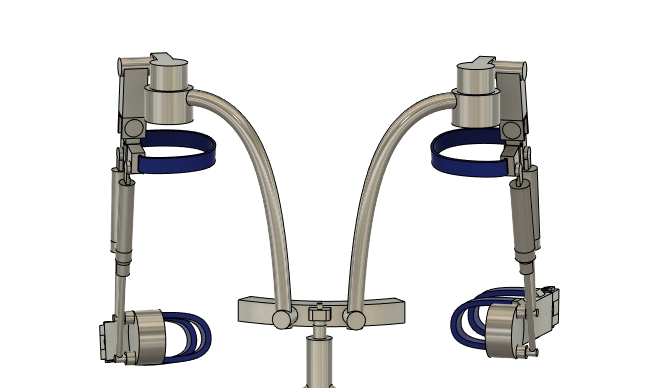
Figure 13: Upper body back view
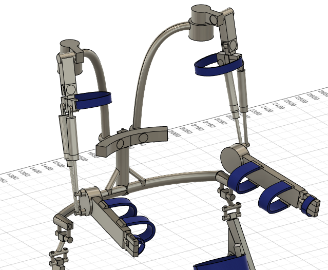
Figure 14: Upper body side view
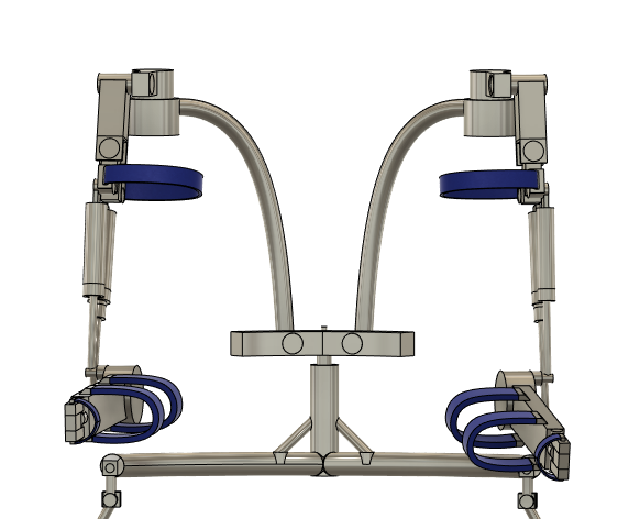
Figure 15: Upper body front view


Lower Back
The design of the lower back has been kept pretty simple. The main function of this part is to connect the shoulder to the lower body to offload the weight. Winged shape tubes were designed which are connected to a T shaped structure which is supported by beams. These beams are connected to a large vertical structure connected to the legs. All design decisions here were taken to keep the skeleton simple, lightweight but strong enough to carry the loads, different angles, heights and thicknesses were tested and the versions which had the highest safety factors (were able to best whistand the load) were picked. The load bearing capability testing using CAD Autofusion will be covered later.
Shoulders
The shoulder was modeled to incorporate the 3 required degrees of freedom. The top cylinder is able to do 360 degrees of rotation, the rotation is only limited by the body of the user. Attached to the cylinder is another cylinder which handles the movement of moving your arm up or down in front of you. Attached to this cylinder is the last cylinder which handles the movement of moving your arm up or down on the sides of your body. With these degrees of freedom the user should be able to put his arm in any position necessary to operate the tools required for his job. Realistically though the placement of these joints in not entirely anatomically correct. Ideally the center of rotation of these joints are in alignment with the center of the actual shoulder joint [47]. The shoulder joint is in practice one of the hardest joints to design both due to the many rotational directions and the limited space around the joint due to the users body getting in the way. There have been many studies modelling the shoulder joint, ideally we would have a better designed shoulder joint such as [47] which includes detailed calculations of human kinematics and vectors such that the design is accuratly aligned with the shoulder joint while also including the required degrees of freedom. [48] Shows a different approach using a double scizor joint which could be another interesting option, completely bypassing the shoulder joint and realizing the degrees of freedom in a completely different way. Figure 16 shows the shoulder joint.

Elbow joint/upper arm
Another very important structure of the design is the upper arm connected to the elbow joint. This is another joint powered by hydraulics because this is were all the lifting actually happens. The design is shown in more detail in the figure 17. There are two hydraulic cylinders attached to a circular joint at the elbow. The hydraulics are also attached to cylindrical joints themselves to be able to move in conjunction with the elbow joint. When one cylinder contracts, the other one extends, thereby creating a circular motion by pulling on the joint, moving the lower part of the arm up or down. This motion is shown in the animation 2. With this design we were able to get a range of motion from fully stretched 0 degree to a 80 degree contraction. This should be enough for getting into most positions when you take into account the range of motion of the shoulders.


Lower arm/wrist
The design of the lower arm is quite simple. A long bar connects the elbow joint to the wrist. Attached to this bar are two straps since it is important that this part of the exoskeleton is attached tightly to the arm to reduce friction and improve accuracy while handling the tools. On the end there is an extra part attached which also has a strap that goes around the wrist. This part is specially made to provide support to the wrist since this has to carry a large part of the load. We want this load to be caught by the hydraulics, thus we need to make sure that these parts are tightly secured to the body such that the forces are applied to your arm.
Full Design Recap


Proof of Concept
Taking the required forces calculated in the section before we get the following values for the different joints.
- 85.87 Kg on the shoulder joint
- 126.50 Kg on the elbow joint
- 75 Kg on the knee and hip joint
Stress test simulations have been run on the CAD model with these forces. The results can be seen below.
Figure 9: Displacement when carrying 20kg
Figure 10: Safety factor when carrying 20kg


CAD has its own safety factor. The safety factor is a ratio of the maximum allowable stress, which is determined by the yield strength of the titanium, in relation to the actual stress on the model. A 1 is needed for an acceptable design but a 3 or higher is desired[49]. Figure 9 shows a simulation of the displacement which happens in the model when the forces are applied to it. The model resulted in only a couple of millimeters displacement on the end of the arms, but more importantly, no breaks at any of the joints or anywhere else in the model. Secondly figure 9 shows the resulting safety factors of the different parts of the model. The minimum safety factor is displayed, which is 5.666. As such we can conclude that indeed our model will be able to withstand all the forces which will be applied to it when carrying the loads calculated above and thus meets the force requirements.
It is also useful to look over the other requirements again and see which ones we were able to achieve. Our first requirement was that the exoskeleton should be able to fit into the police van shown in the transportation requirement. In this section, it was already stated that the requirement would have been in a seated position most likely and since the model has a functioning knee joint that is able to at least go 90 degrees this should be no problem. The movement requirement is the first requirement where some concessions had to be made. While the model does incorporate all the degrees of freedom that were necessary for the movements explained in this section, some concessions were made regarding the total degrees of movement. For example, the elbow joint cannot fully contract to 120 degrees since the hydraulics start getting into each other’s way. Currently, it only goes to 80 degrees which should also be fine since the firemen will not be lifting the tools very high above their waist. Also, the knee joints cannot fully contract due to the same problem but the joints can contract to 90 degrees which is at least enough for sitting of some sort of crouching. For the joints, the focus was essentially on modeling the degrees of freedom, and most of the joints need some better kinematic study of human joint interaction to make them function more optimal which is a possible improvement to our model.
The time requirement is hard to prove, the model has been kept simple and flexible and the straps should make it easy to get in and out of. Taking into account the proper training of firemen on the use of the exoskeleton and how trained they already are with getting in and out of gear, we believe the required time of 4 minutes should be doable.
The support mechanism is handled by the hydraulics but also needs a control system. The last section of general design already covers the control system and the model was proven that it could hold up its own weight so there is a good justification that this requirement can be met.
The material requirement is solved solely by the fact that Autofusion had the material in its library and as such we were able to model with the material thereby proving that the material can hold up to the forces put upon it.
The force requirement is proven with the simulations run in Autofusion explained above in this section. This is the most important part of the proof that the model could function in a real-life setting and as such is also our proudest achievement.
By solving these functional requirements, the user requirements were also addressed. "[UR01] - The exoskeleton shall not hinder the user in their required movements" with its sub-requirement "[UR01.a] - The exoskeleton shall not restrict easy access to the communications device of the fireman." is mostly solved by the design of the model with regards to the degrees of freedom explained earlier, we made sure not to cover and of the front parts of the user's front side of the waist since this is where the communications device would normally be located. For "[UR02] The exoskeleton shall be easy to get into the model" was kept simple and easy straps were designed to take care of this, once again we cannot really prove this as stated above for the time requirement but some measures were at least taken to cater to this requirement. "[UR03] The exoskeleton will make the user able to lift heavy equipment by himself without straining effort." For this requirement, we made the force requirement specifically to make sure the lifting of an object would be easy and require no effort from the user at all, which was proven with the CAD simulations.
Conclusions
Our contributions to the field of exoskeleton technology lie mostly in our thorough user research. Knowing exactly what the users want and need, and asking for their opinions and feedback throughout the project, not just at the beginning, ensures that the final product will not only be usable, but also desirable. Instead of diving head-first into the strongest and most advanced tech might seem fun, but in the end you would end up with an overcomplicated, overpowered and overprized sci-fi suit that no firefighter would ever dream of using. When you instead listen to your users and steer your product in the direction they want, not afraid to make changes, you might not have to use the most advanced tech or invent revolutionary exoskeleton systems, but you will end up with a concept that works.
And that is exactly what we have ended up with, a concept that works for the use case we have chosen. It’s not extraordinarily powerful or complicated compared to some of the exoskeleton technology already out there, but it incorporates the needs of our users very well. It’s relatively lightweight, compact, flexible and mobile, all of which are very important for firefighters.
But as stated, our final product is a concept, one we know will work, but it’s not ready to go to be manufactured just yet. The design still needs a lot of mechanical engineering to make it an efficient and elegant design, something we could sadly not achieve with our limited skillset and timeframe. Still, the proof is there that an exoskeleton like this would find a home in every fire station in the Netherlands.
Reflections
Overall, we are very pleased with our exoskeleton as it is now. We have a lot of confidence in this project, because we have proven an exoskeleton such as we’ve designed would be both desirable and possible. But a project is never without its hiccups, and this year I think everyone’s project has had the biggest hiccup in decades.
The difficult times everyone has been dealing with these past couple of months have of course impacted this project a lot. In the beginning it took a little bit of time to get used to working together with a team of people you’ve never seen in real life. But every problem just gives opportunity for new solutions and you end up honing your teamwork skills that much more. Of course we also had to show our best engineering side as we all had to work from home.
Once the ball got rolling though, our project started to take shape quickly and we all got excited to keep working on it. We’re very proud of the amount of user research we were able to do even though we were in quarantine and it really steered our project in a certain direction we had not foreseen, or even thought of.
In the end our flexible workflow in this project is probably what taught us the most these past few weeks. We gained a lot of experience in working together with people from different backgrounds within our team, as well as working together with users. The ability to listen, adapt and be flexible with your deliverable was a valuable lesson for all of us.
Approach, milestones & deliverables
Approach
Our current goal for the end deliverable is a model for an exoskeleton that helps emergency services. Due to the COVID-19 situation, the process of the actual building of the model will be difficult in the given time span. The aim is to have a full-body exoskeleton that has both a passive and active mode to preserve battery. We want to achieve this by reaching the milestones as mentioned below. In short, we want to research what has already been achieved in the field of exoskeletons and how they operate. After that, we want to start designing our model and elaborate on our design choices in a report. This model will be made using CAD software which we yet have to determine. Since we have plans for a full-body exoskeleton we will distribute this work amongst two of our group members. The rest of the group will work more on the research and design choices of the project. If we find out that this distribution of work is not working out for us, we will alter it accordingly.
Milestones
| Week | Milestone |
|---|---|
| Week 1 | Research on possible projects and prepare for the first meeting |
| Week 2 | Summarize papers & more research
First design decisions |
| Week 3 | Learn CAD
Elaborate research on design decisions |
| Week 4 | First CAD concept designs
Finish research & write the report |
| Week 5 | Finalize design
Elaborate design sections in the report |
| Week 6 | Finalize CAD models
Finish design sections in the report |
| Week 7 | Finish video presentation
Final report on the wiki page |
| Week 8 |
Video presentation and peer review |
Deliverables
Our deliverables will be:
- A concept design for a flexible, multipurpose exoskeleton that uses passive and active technology for use by emergency services.
- A report on the wiki page containing a detailed description of the design as well as all of the research, findings, and results of the project.
- A video presentation presenting our research, findings, and design.
Task distributions
Bengt and Matthijs will focus on learning CAD and visualizing our designs. As mentioned before, there will be somebody (Max) who can help with this if there are too few group members assigned to this task. Max, Pim, and Thomas will do research on how the exoskeleton will be made. This consists of e.g. the materials, electronic circuits, and passive mechanisms.
Logbook
Week 1:
| Name (ID) | Hours | Work done |
|---|---|---|
| Matthijs Marinus (1000921) | 8 | Intro lecture[1h] Meetings [3h], Finding/Researching different topics [4h] |
| Bengt Frielinck (1269593) | 8 | Intro lecture[1h] Meetings [3h], Finding/Researching different topics [4h] |
| Pim Claessen (0993712) | 7 | Intro lecture[1h] Meetings [3h], Finding/Researching different topics [3h] |
| Max Opperman (1232427) | 7 | Intro lecture[1] Meetings [3h], Finding/Researching different topics [3h] |
| Thomas Willems (1022753) | 7 | Intro lecture[1] Meetings [3h], Finding/Researching different topics [3h] |
Week 2:
| Name (ID) | Hours | Work done |
|---|---|---|
| Matthijs Marinus (1000921) | 11 | Meetings[30m], Researching new topic for user groups [2h], Writing user groups/SoTA part/updating wiki page[3h30m], Installing CAD Fusion360/Doing tutorials on modelling[5h] |
| Bengt Frielinck (1269593) | 9 | Communications[30m],Researching[2h], Writing requirements and revision[2h30m], CAD Training[4] |
| Pim Claessen (0993712) | 5.5 | Meetings[2h], Writing Problem Statement [30m], Research [3h] |
| Max Opperman (1232427) | 9 | Meetings[2h], Writing Approach, Milestones and Deliverables/updating wiki page[3h], Writing requirements[2hr], Research on lifting abilities for requirements [1hr], Research on how to write proper requirements [1hr] |
| Thomas Willems (1022753) | 4 | Meetings[2h], Writing Approach, Milestones and Deliverables/updating wiki page[2h] |
Week 3:
| Name (ID) | Hours | Work done |
|---|---|---|
| Matthijs Marinus (1000921) | 10.15 | Meetings [2h], Contacting Eindhoven firedeparments, Interview [45min], Write on wiki (small update SoTa, writing user requirments form interview, researching/elaborating requirements) [4h], CAD tutorials [3:30h]) |
| Bengt Frielinck (1269593) | 10 | Meetings [2h], Requirements[2h],CAD Tutorials[6h], CAD prototype[2h] |
| Pim Claessen (0993712) | 7.5 | Meetings [2h], Writing out requirements [3h], Researching batteries and exoskeletal joints [2h], Editing wiki [0.5h] |
| Max Opperman (1232427) | 8 | Meetings [2h], Writing requirements [4h], Editing wiki [2h] |
| Thomas Willems (1022753) | 6 | Meetings [2h], Contacting police- and firedepartments [2.5], Writing interview questions [1h], Editing wiki [30m] |
Week 4:
| Name (ID) | Hours | Work done |
|---|---|---|
| Matthijs Marinus (1000921) | 7h30 | Meetings [2h], Research upper body skeletons [3h], Research CAD simulations and tutorials [2h30m] |
| Bengt Frielinck (1269593) | 7h | Meetings [2h], Requirements[1 h],CAD Tutorials[2h], CAD prototype[2h] |
| Pim Claessen (0993712) | 8 | Meetings [2h], Researching firefighter equipment [1h], Researching human body [1h], Researching Force requirement [1h], Researching materials [2h] Editing wiki [1h] |
| Max Opperman (1232427) | 7 | Meetings [2h], Writing requirements (elaboration and link to use cases; research + calculations for heat and materials) [3h], Editing wiki [2h] |
| Thomas Willems (1022753) | 7 | Meetings [2h], Interviewing William Elseman [2h], writing user research [2h], editing wiki [1h] |
Week 5:
| Name (ID) | Hours | Work done |
|---|---|---|
| Matthijs Marinus (1000921) | 11 | Fusion tutorial joints/modelling upper body skeleton [6h30], researching/writing/updating wiki movement requirements [2h30], Meetings[2h] |
| Bengt Frielinck (1269593) | 16 | Meetings [2h],CAD Tutorials[4h], CAD prototype[10h] |
| Pim Claessen (0993712) | 11 | Meetings [2h], overall theoretical desing exoskeleton [1], Researching firefighter equipment [1h] researching walking [3h], researching hydraulics [3h], researching force requirement [1h] |
| Max Opperman (1232427) | 10 | Meetings[2h], Updating wiki [2h], Size research [3h] Researching/writing transportation requirements [2h], Writing requirements section[1h] |
| Thomas Willems (1022753) | 10 | Meetings [2h], Interview with Gijs Craenmehr [5h], Writing Wiki for User Research [3h] |
Week 6:
| Name (ID) | Hours | Work done |
|---|---|---|
| Matthijs Marinus (1000921) | 9h30min | Meetings [2h], extending research movement requirement (updating with better sources and pictures)[3h], re-doing the time requirements for transporting [30min], finding/reading/summarzing more articles for SoTA [4h] |
| Bengt Frielinck (1269593) | 16 | Meetings [2h],CAD Tutorials[4h], CAD prototype[10h] |
| Pim Claessen (0993712) | 9.5 | Meetings [2h30m], overal theoretical design exoskeleton [2h], writing force requirement [3h], making force figures [1h], updating wiki [1h] |
| Max Opperman (1232427) | 9 | Meetings [2h30m] Updating main requirement [1h], State of the art research & updating Wiki [5h], Writing video script [30m] |
| Thomas Willems (1022753) | 9 | Meetings [2h30m], Contacting users about scenario's [2h], Writing User Scenario's [4h30m] |
Week 7:
| Name (ID) | Hours | Work done |
|---|---|---|
| Matthijs Marinus (1000921) | 17h | Meetings [2h], CAD (replacing feet, extending upper/lower leg compontents with plates, making hydraulics design, shortening shoulder joint) [11], Writing lower body design (getting screenshots, writing text, finding sources, updating wiki)[4h] |
| Bengt Frielinck (1269593) | 22 | Meetings [2h], CAD prototype[20h] |
| Pim Claessen (0993712) | 8.5 | Meetings [2h30m], writing force requirement [3h], writing/updating requirements [2h], updating wiki [1h] |
| Max Opperman (1232427) | 5 | Meetings [2h], Writing script for video (user research) [1h30m], Writing script for video (requirements) [1h30m], Setting up for video presentation [1h] |
| Thomas Willems (1022753) | 7 | Meetings [2h30], Writing script for video (intro, scenario's, design,) [3h30], making powerpoint for video [1h] |
Week 8:
| Name (ID) | Hours | Work done |
|---|---|---|
| Matthijs Marinus (1000921) | 13:45 | Meetings [2h], Researching/writing updating wiki on design [5h], writing reflection of requirements [45min], fixing wiki images and styling [5h] and re-writing parts of movement requirement, proofreading [1h] |
| Bengt Frielinck (1269593) | 12 | Meetings [2h], CAD prototype[10h] |
| Pim Claessen (0993712) | 8 | Meetings [2h], proof reading wiki [1h], polishing requirements [1h], updating wiki [4h] |
| Max Opperman (1232427) | 18 | Meetings[2h], Recording talk for video [2h], Updating some minor mistakes in Fusion for video [1h], Recording video in Fusion [3h], Fetching footage for video [3h], Editing video [5h], Updating Wiki [2h] |
| Thomas Willems (1022753) | 12 | Meetings [2h], Recording for video [3h], Writing on wiki (conclusion and reflection) [3h], Cleaning up wiki [4h] |
References
- ↑ [1]: Health glance Europe. (Retrieved April 29, 2020)
- ↑ 2.0 2.1 [2]: Extrication from Cars during
Road Traffic Accidents. (Retrieved April 29, 2020) Cite error: Invalid
<ref>tag; name "Extrication from Cars during Road Traffic Accidents" defined multiple times with different content - ↑ [3]: Firefighter fatalities in the United States - Firefighter death by cause and nature of the injury, National Fire Protection Agency. (June 2019) Retrieved April 27, 2020
- ↑ [4]: Summary incident report, US fire administration (21 April, 2020) Retrieved April 27, 2020
- ↑ 5.0 5.1 [5]: Auberon Pneumatic Exoskeleton, Trigen Automotive. () Retrieved April 27, 2020
- ↑ 6.0 6.1 [6]: Power Suit for Disaster Relief: Robot Exoskeleton From German Bionic Supports Rescue Teams During Challenging Missions, PR Newswire. (19 December 2018) Retrieved April 27, 2020
- ↑ 7.0 7.1 [7]: Exoskeleton Technology’s Impact on Policing, Journal of California law enforcement. (February 2017) Retrieved April 27, 2020
- ↑ [8]: Back-Support Exoskeletons for Occupational Use: An Overview of Technological Advances and Trends, ResearchGate. (August 2019) Retrieved April 27, 2020
- ↑ [9]: Robotic Exoskeletons: The current pros and cons, World Journal of Orthopedics. (18 September 2019) Retrieved April 27, 2020
- ↑ [10]:Fire exoskeleton to facilitate the work of the fireman. (2019) Retrieved May 13, 2020
- ↑ [11]D. Sasaki and M. Takaiwa, "Development of pneumatic power assist wear to reduce physical burden," 2014 IEEE/SICE International Symposium on System Integration, Tokyo, 2014, pp. 626-631, doi: 10.1109/SII.2014.7028111.
- ↑ [12]M. Bolignari, G. Moretti and M. Fontana, "Design and Experimental Characterisation of a Hydrostatic Transmission for Upper Limb Exoskeletons," 2018 IEEE/RSJ International Conference on Intelligent Robots and Systems (IROS), Madrid, 2018, pp. 2768-2773, doi: 10.1109/IROS.2018.8593639.
- ↑ 13.0 13.1 [13]Nicola Vitiello, Member, IEEE, Tommaso Lenzi, Student Member, IEEE, Stefano Roccella, Stefano Marco Maria De Rossi, Student Member, IEEE, Emanuele Cattin, Francesco Giovacchini, Fabrizio Vecchi, Member, IEEE, and Maria Chiara Carrozza, Member, IEEE (February 2013). NEUROExos: A Powered Elbow Exoskeleton for Physical Rehabilitation.
- ↑ 14.0 14.1 [14]Bongsu Kim and Ashish D Deshpande, (2017), An upper-body rehabilitation exoskeleton Harmony with an anatomical shoulder mechanism: Design, modeling, control, and performance evaluation
- ↑ 15.0 15.1 [15]Bai, Shaoping Virk, Gurvinder S. Sugar, Thomas G.. (2018). Wearable Exoskeleton Systems - Design, Control, and Applications. Institution of Engineering and Technology.
- ↑ [16]Dutch: Percentage of female firefighters in the Dutch fire brigade.
- ↑ [17]Dutch: Average length of Dutch people.
- ↑ [18]Average proportions of the weight and length of body segments of a human
- ↑ [19]Dutch: Average width and depth of a human
- ↑ [20]: Ramon Versteeg on Twitter "New VW Transporter T6 for the Wezep fire brigade. Among other things, it is used for surface rescue."
- ↑ [21]: Size of the trunk of a Volkswagen Transporter
- ↑ [22]: Dr Arun Pal Singh, Degrees of Freedom Upper Limb, (Retrieved June 30, 2020)
- ↑ [23]:Joel C. Perry, Jacob Rosen, Member, IEEE, and Stephen Burns, Upper-Limb Powered Exoskeleton Design, (August 2007) Retrieved June 02, 2020
- ↑ [24]: Watkins, James. (2017). Developmental biodynamics: the development of coordination.
- ↑ 25.0 25.1 [25]: Cynthia C. Norkin, Joint Structure and Function: Chapter 8, ()
- ↑ [26]: Ning Li, Liang Zhao, Peng Yu, Ning Xi, Bio-inspired wearable soft upper-limb exoskeleton robot for stroke survivors, (December 2017)
- ↑ [27]: Jianfeng Li, Ziqiang Zhang, Chunjing Tao, and Run Ji, A number synthesis method of the self-adapting upper-limb rehabilitation exoskeletons, (June 2017)
- ↑ 28.0 28.1 28.2 28.3 [28]: Nancy Hamilton, Ph.D., Wendi Weimar, Ph.D., Kathryn Luttgens, Ph.D., Kinesiology: Scientic basics of human motion 12e
- ↑ [29]:Adam Zoss, H. Kazerooni, Andrew Chu, On the mechanical design of the Berkeley Lower Extremity Exoskeleton (BLEEX)
- ↑ 30.0 30.1 [30]:Karl E. Zelik, Kota Z. Takahashi, Gregory S. Sawicki, Six degree-of-freedom analysis of hip, knee, ankle, and foot provides an updated understanding of biomechanical work during human walking
- ↑ [31]: Subhasis Bhaumik, Shahid Ansari, Ritwik Chattaraj: Motion for lower limb Exoskeleton based on predefined gait data, ( October 2016)
- ↑ 32.0 32.1 [32]:Statline, Branden; reactietijden van de brandweer, regio, (20 March 2020)
- ↑ [33]: Dutch source for heat resistance of firefighter suits
- ↑ [34]: Frontal area of a person standing
- ↑ [35]Titanium Grade 6 Properties
- ↑ [36]Titanium Beta C Properties
- ↑ [37]Titanium G5 Annealed Properties
- ↑ [38]Differences in heat treatment of materials
- ↑ [39]Titanium G5 STA Properties
- ↑ [40]Carlisle 201LL Carbon-Carbon Composite
- ↑ [41]Carlisle 201LD Carbon-Carbon Composite
- ↑ [42]: Body segments data. (Retrieved April 29, 2020)
- ↑ [43]: waling force. (Retrieved April 29, 2020)
- ↑ 44.0 44.1 [44]: Kok-Meng Lee, Fellow, IEEE, Donghai Wang, Design Analysis of a Passive Weight-support
Lower-extremity-exoskeleton with Compliant Knee-joint, (May 26-30, 2015) Cite error: Invalid
<ref>tag; name "ExampleKneeJoint" defined multiple times with different content - ↑ [45]:Suit X
- ↑ [46]:Wei YANG, Can-jun YANG, Ting XU, Human hip joint center analysis for the biomechanical design of a hip joint exoskeleton, ( Jan 13, 2016;)
- ↑ 47.0 47.1 [47]Randa Mallat, Mohamad Khalil, Gentiane Venture, Randa Mallat, Vincent Bonnet, Samer Mohammed: Human-Exoskeleton Joint Misalignment: A Systematic Review. (2019)
- ↑ [48]Miguel Nobre Castro, John Rasmussen, Michael Skipper Andersen, Shaoping Bai: A compact 3-DOF shoulder mechanism constructed with scissors linkages for exoskeleton applications. (February 2019)
- ↑ [49]: Safety Factor, CAD Autofusion 360