PRE2017 3 Groep13
Problem Statement
People with visual impairments have trouble navigating through space due to the absence of clear sight. Nowadays, they have to trust on their dog who is guiding them across the streets. This people have also a blind stick to feel what object are in their close environment. However, they can not feel if there is a doorstep or a lamppost at the same time, what can cause a insecure feeling. They have to walk slowly because of their short field of view. This problems make it intensive to walk outside. It also occurs that blind people don’t like dogs or even are allergic for them. Improvements for the way blind people are detecting the environment can be made. By means of this project a possibility for improvement will be examined.
Users
The users are people with visual impairments. For them, the wearable have to replace the stick and/or guiding dog. In this way, it is possible for the user to walk around with free hands. If possible, we will contact a person with visual impairments, so a potential user can influence the design of the product. The goal is to make a user-centered design.
There are also secondary users. This are the other persons who are also in the same environment as the visual impaired. This are in our case the other persons who are working in the office or drinking coffee in the room with chairs, tables and bags. For them, it is important that the wearable is not annoying to have around.
Scenario
A office space with obstacles (tables, seats etc.) in which a blind(folded) could walk around with our device without hitting any of the obstacles. For example a blind person should be able to navigate through the room from the coffee machine to his/her seat without hitting other seats, tables, bags or persons.
To test we could blindfold a group member and set the obstacles so he/she cant see where they are. Then the test subject has to navigate through the room, if any obstacles are hit the device is not working properly yet. The test subject should be able to walk around for circa 5 minutes.
Specific test environment
For the test with the belt, we will use chairs, tables and bags. This is because we want to see if a blind person could walk through the room without walking into tables or chairs, and also bags should be noticed so the person won’t trip over them. One of the group members will be the test subject and will wear a blindfold. Furthermore this person will wear the belt on either the hips or the belly, depending on what that person prefers and on if the sensors will be at the right position (this will be explained later). Then the room is randomized so the person doesn’t know what the situation is to make it more realistic. The test person will then try to walk through the room without hitting any objects, this is very similar to the tests we have already done to determine what feedback is preferred and what works the best (this complete test is described elsewhere).
State-of-the-art
Bousbia-Salah suggests a system where obstacles on the ground are detected by an ultrasonic sensor integrated into the cane and the surrounding obstacles are detected using sonar sensors coupled on the user shoulders. Shoval et al. proposes a system which consists of a belt, filled with ultrasonic sensors called Navbelt. One limitation of this kind of system is that it is exceedingly difficult for the user to understand the guidance signals in time, which should allow walking fast. Another system using a vision sensor is presented by Sainarayanan et al. to capture the environment in front of the user. The image is processed by a real time image-processing scheme using fuzzy clustering algorithms. The processed image is mapped onto a specially structured stereo acoustic pattern and transferred to stereo earphones. Some authors use stereovision to obtain 3D information of the surrounding environment. Sang-Woong Lee proposes a walking guidance system which uses stereovision to obtain 3D range information and an area correlation method for approximate depth information. It includes a pedestrian detection model trained with a dataset and polynomial functions as kernel functions (Vitor Filipe). [5]
Ghiani, Ieporini, & Paternò designed a multimodal mobile application considering museum environments(2009). They extended the vocal output with haptic output in form of vibrations. It was tested if participants prefered discontinuous output or continuous output differing in intensity using a within-subject design. The results implied the participants prefered the discontinuous variant, but the results were non-significant. [6]
Deliverable
A prototype of the device will be made. This will be a wearable. Also a report of the project will be updated weekly on wiki.
Specifications and requirements
We want to make a device that helps people with visual impairments to navigate through space. The device has to meet the following requirements:
- It detects the ground in front of the feet (1.5 m). In this way, the blind doesn’t have to be afraid to stumble over bags etc. 1.5 meter is also enough to walk faster, the device gives feedback soon enough, so the blind person can slow down easily.
- It detects the environment up to waist height. In an office the most common obstacles are chairs, tables and bags. For this, detection up to waist height is enough. We also make the assumption that higher obstacles are standing on the floor. In this way they will be detected as well by a sensor up to waist height (i.e. closet).
- The feedback signal scales with the distance of the obstacles. It gives a bigger signal in case the obstacle is closer to the blind person, in this way the blind person knows how far he can walk before bumping into the obstacle. In case the device gives a big signal but the blind doesn’t feel an obstacle, he knows that his clothes are hindering the sensor.
- By the feedback, the blind person has to know in which direction the obstacle is located (left, right, in front of). For this, the detecting bundles must be narrow (15-30 degrees). The total detecting area have to be 60 degrees.
- The feedback signal can be turned off (on/off button). In case the blind person is sitting at the table, the signal can be turned off. The blind person is not bumping into obstacles because he isn’t walking. It is also annoying that the feedback signal will go on and on because the device detects the table continuously.
- The time delay between obstacle detection and the feedback signal have to be short (30 ms).
- It have to be visible for the environment that the user is a blind person, so other persons can take it into account.
- The feedback signal have to be humanly and easy to understand.
- During the test, a blindfolded person has to walk with the device for at least 5 minutes (battery life).
- A blind person should be able to put the device on by himself
The device has to meet the following specifications:
- At least 4 sensors and 4 vibration motors
- The belt has to be 4 cm wide and 90 cm long
- The belt has to be made of soft material, this is needed for attaching the sensors
- The sensors will be attached at the outer side of the belt
- The vibration motors will be attached at the inner side of the belt
- The wire connections will be made behind the belt.
- The sensors will have an angle of 40 degrees relative to the belt
- The arduino can be stored in a pocket
- The reach of the sensors has to be 1 meter
- The sensors should not have to pass through the loops on a pants
Objective
Making a device that makes it more easy and less intensive for blind people to navigate through space.
Approach
An user-centered design (if possible) of a device that helps blind people navigating through space. This can be done by making a device that gives more information about the close environment of the user. The user have to get information about obstacles by their feet and head/other body parts at the same time. A point for orientation is needed so the user knows in which direction he/she walks. To know what the best options are to make device easy and comfortable to use a blind person will be contacted. After designing a device that meets the requirements a prototype of this device will be made. For this, the following milestones have to be achieved:
Milestones
- Literature study
- Finishing the design of the prototype
- Components for prototype are arrived
- Device is built and the software is made
- The device works and functions well (functioning testing)
- The device is usable (usability testing)
Who’s doing what and roles
Planning
Week 1: literature study (all), asking experient permission for usability testing (Eline), writing the problem statement (Evianne), make planning (all), determining roles (all), making requirements (all)
Week 2: Think about specific scenario and problem (all), make specifications and requirements (Evianne)
Week 3: interviewing user (Eline), making design of the device (Eline and Evianne), making bill of materials (Stefan, Tom, Bruno), updating wiki (all)
Week 4: Write scenario (Bruno), make planning for this week (Tom), think about design (Evianne), update wiki (Evianne), make bill of materials (Stefan), answer coaching questions (Tom), doing specific literature research (Tom), taking care of budget (Eline), write technology (Eline)
Week 5: Order bill of materials (Stefan), programm the feedback system (Stefan), better the design (Evianne), build on prototype (Tom, Eline Bruno)
Week 6: completing tasks that are not finished yet (all), testing the feedback system of the wearable (Eline)
Week 7: Finishing the prototype (all), final presentation (Eline)
Week 8: Ordering the wikis (all)
Who is doing what
Eline : Designing, usability testing, literature study - point of contact
Stefan: Programming, literature study - checks the planning
Tom: Assembling, selecting products, literature study - prepare meetings
Bruno: Assembling, selecting products, literature study - making minutes
Evianne: Human-machine interactions, designing, usability testing, literature study - checks wiki
Roles
Eline : Point of contact
Stefan: Checks the planning
Tom: Prepare meetings
Bruno: Making minutes
Evianne: Checks wiki
Literature research
The topics needed for the project are split up. Everybody have a direction at which he/she gathers information.
Eline: - usability testing, universal design
Evianne: - Just Noticeable Difference, human skin, ethics
Bruno: - electromagnetics, hall effect (car sensors)
Tom: - developed aid devices, optical sensors
Stefan:- (digital) compass, infrarood
Spatial discrimination of the human skin
Surfaced have often to be smooth, i.e. food textures have to feel smooth for users. Healthy human are tested in roughness sensation. Obtained results showed that human’s capability of roughness discrimination reduces with increased viscosity of the lubricant, where the influence of the temperature was not found to be significant. Moreover, the increase in the applied force load showed an increase in the sensitivity of roughness discrimination. [1]
Pain in the skin can be localized with an accuracy of 10-20 mm. Mechanically-induced pain can be localized more precisely then heat or a non-painful touch. Possible due to two different sensory channels. The spatial discrimination capacities of the tactile and nociceptive system are about equal. [17]
There are two categories for thermal discrimination. A rising or a falling temperature and temperatures above or below the neutral temperature of the skin. Sensing temperature happens by myelinated fibers in nerves.[11]
The homing behaviour of Eptesicus fuscus, known as the big brown bat, can be altered by artificially shifting the Earth's magnetic field, indicating that these bats rely on a magnetic compass to return to their home roost. Homing pigeons use also the magnetic field for navigation. [8]
Localization
Indoor localization can be achieved using a beacon system of ultrasonic sensors and a digital compass. Although ultrasonic sensors are very sensitive to noise or shocks these disadvantages can be mitigated by using a band pass filter (H. Kim, J. Choi 2008). Generally the use of an Unscented Kalman Filter further improves accuracy of measurements. [9]
The use of the digital compass inside a smartphone can be used to track head movement. Then that can be used to reproduce a virtual surround sound field using headphones (S. You, Y. Wu 2017). Applying such a system to blind people could help them navigating by producing sounds which come from a certain direction without other people hearing it. [20]
It is shown that a digital compass can give accurate readings using a RC circuit, ADC and a Atmega16L MCU (S. Qu, L. Nie, W. Li 2011). Furthermore by slowly rotating the compass to measure the magnetic field inference can further improve accuracy. S. Qu, Li. Nie and W. Li showed the entire design of such a compass. [19]
If it is known in which plane the compass is being turned, it can be used to further reduce errors (Z. Lijie, C. Ji, 2011). However these solutions were applied to micro-unmanned air vehicle which do require very precise readings. Applications helping blind people might not need these precise readings. [25]
An application of digital compasses might be the orientation of a robotic arm. C. Marcu, G. Lazea, D. Bordencea, D. Lupea and H. Valean showed how an entire system using digital compasses could be built, addressing multiple issues mainly on a high-level without going too much into the details. They showed how to convert the coordinates using the readings of the compass. [16]
Usability testing and universal design
To implement User-Centered Design, it is important to define the term usability. Usability has been interpreted in many different ways, but Alonso-Ríos, Vázquez-García, Mosqueira-Rey, & V. Moret-Bonillo defined a clear and extensive usability taxonomy (2009). [2]
Usability Testing is effective in helping developers produce more usable products (Lewis, 2012), which comes in handy in this project. This chapter explains types to do Usability Testing, like thinking aloud which is quite easy but gives a lot of information. Furthermore, several examples are presented. [15]
Especially when involved with people with impairments, it is important to make a universal design. As Story, Mueller, & Mace mention in chapter 2 of their book, there are a lot of things to consider if a design should be universal. (1998) [22]
In chapter 3 of their book, Story, Mueller, & Mace state seven principles (1998). When these principles are followed, the design will be universally usable. Also, a lot of examples are provided in this chapter. [21]
Developed aid devices and optical sensors
The application of robotics to a mobility aid for the elderly blind [7]
The objective of robot mobility aid is to let blind people regain personal autonomy by taking exercise independent of people who care for them. The perceived usefulness rather than usability is the limiting factor in adoption of new technology. Multiple impairments can be tackled at the same time, in the paper the device works as a mobility device and walking support. Preferable is that the user is in control of what happens, or that the robot decides what happens, but not something in between as that leads to confusion. Also users prefer voice feedback over tonal information, perhaps because it is more human-like (Giudice, N. A., Legge, G. E.).
A Tool for Range Sensing and Environment Discovery for the Blind [24]
A device is created which uses a laser to calculate distances to objects. This could help the user to decide where to move, but is not sufficient for safe deambulation. The device would work as a virtual white cane, without using the actual invasive sensing method of the white cane. It uses active triangulation to produce reliable local range measurements. Objects can be found, but it is still hard to translate this to the user (Yuan, D., Manduchi, R.).
New Developments in Mobility and Orientation Aids for the Blind [4]
The long cane (white cane) is still the primary mobility aid for the blind. New electronic mobility aids mostly use the transmission of an energy wave and the reception of echoes (echo-location) from objects in or near the user’s path. Optical transmission is another highly used concept. As wavelength is the limiting factor in detection of small objects, optical transmission has advantages. One class of aids is known as the “obstacle detectors”, other aids attempt more than only obstacle detection, by using for example auditory output to show the way. Also incorporating he sensing on the skin has been researched. Lastly there is the area of cortical implants (Brabyn, J.A.).
Blind Navigation and the Role of Technology [12]
The most important difference between visual navigation and blind navigation is that visual navigation is more of a perceptual process, whereas blind navigation is more of an effortful endeavor requiring the use of a cognitive and attentional resources. Some technologies work better in other environments. Also aesthetics are of impact on the user. The long cane and guide dog are the most common tools of navigation, other aids are mostly used to complement these tools. Other devices are based on sonar detection, optical technologies, infrared signage, GPS-based devices, sound devices and some tools for indoor navigation (Kay, L.).
An ultrasonic sensing probe as a mobility aid for the blind [13]
It is quite hard to get a clear understanding of a possible environment via echo location or ultrasonic sensing. Under specific conditions objects were located with echo location. Different environments give very different amounts of perception. Moreover was it needed for users to learn to use the device. Learning to interpret the sounds did not necessarily improve mobility. Objects could be detected, but users had to still learn how to avoid them. Also, as hearing was used for echo location, normal use of the hearing sense was slightly impaired (Lacey, G., Dawson-Howe, K.M.).
Electromagnetics and sensors
Proximity sensors can detect the presence of an object without physical contact. There are many variations of these sensors but 3 basic designs exist: electromagnetic, optical, and ultrasonic. The electromagnetic types are subdivided into inductive and capacitive sensors. However these work with metal. Optical proximity sensors use one of two basic principles, reflection or through-beam. Here shiny surfaces can cause trouble. Ultrasound works similar, in respect that sound also reflect on objects, which can be measured. Here objects that do not reflect it back can cause trouble. [18] [23]
In the article of Benniu, Zhang; Junqian, Zhang; Kaihong, Zhang and Zhixiang, Zhou a non-contact proximity sensor that is able to detect any kind of material with low frequency electromagnetic field. [3]
In the article of M.R.Jackson, R.M.Parkin and B.Tao, a medium range radar sensor is proposed, however this is for a distance too big for our purposes. [10]
Yang‐Sub Lee and Mark F. Hamilton mainly discuss the ideal circumstances for an ultrasonic sensor in air. [14]
Literature about sensors to observe objects
1. Short distance ultrasonic distance meter [26]
A short distance ultrasonic distance meter device is made to detect objects at short distances. When a object is detected the device starts to ring, if an object cannot be observed because it is too far away, anti feedback makes sure ringing is cancelled. Also opposite phase methods are used to provide the same purpose. Lastly both are used to receive optimal results.
2. Parking aid with a wheel sensor [27]
The distance of obstacles at near range to a motor vehicle are determined with a displacement sensor instead of an ultrasonic measurement. The distance is measured above a predetermined limiting value. By comparing the signals of the displacement sensor and the ultrasonic measurement a calibration and correction factor for the displacement sensor can be obtained.
3. Vehicle blind spot detector [28]
A driver in a car always has blind spots where he cannot see if there is an object. Those blind spots cannot be observed through the mirrors. To solve the problem a sequentially operating dual sensor technology is used. The first sensor takes place as a photonic event. Infrared light emitted by an IRLED is coupled to an infrared light sensitive phototransistor or photo-darlington. Once the reflected infrared light is detected a second sensor is activated. The second sensor works with ultrasonic waves. The driver can then be given the distance between the vehicle and the threat obstacle.
Design
There is made a design of the prototype that meets the specifications. One of the specifications is that the obstacles in front of the feet and the obstacles at waist height have to be detected. It will be easy if the wearable is being carried at the same height. The legs and feet are not stable enough to detect a specific area in a constant manner. For this, we thought about a belt, which is also easy usable and could also be used to indicate that the wearer is blind.
The sensors can be implemented in the belt. These sensors can detect the area in front of the feed and at waist height. For this, the bundle has to shine downwards in an angle of 20-90 degrees relative to a vertical line (the user). If the bundle comes closer to the user that 20 degrees, the sensors will detect the legs and feets while walking around. The 90 degrees are needed for detection of obstacles at waist height.
One of the specifications is that the user has to know in which direction the obstacle is located. For this, we need three sensor bundles to indicate the location of the obstacle, right, left or in front of. It will be annoying when the belt is constantly giving feedback in case there walks someone next to the blind person or in case the hands of the user are hindering the sensor. We also make the assumption that users only walk straight ahead or walk along gently curves. For this, detection of obstacles in a straight line beside of the user will give unusable feedback. We choose for a sensor bundle with a width of 60 degrees. In this way, the user has room to move his hands without hindering the sensors. Also, unnecessary feedback will be reduced. This area of 60 degrees has to be split up in three sub areas. Obstacles in front of the user are most important to detect for preventing an accident. The 60 degrees can be split up in a front of-bundle of 30 degrees. The left and right bundle will have a width of 15 degrees. The feedback signal scales with the distance of the obstacles, so in case the hands or clothes are hindering the sensor the user can conclude what is going on when they don’t feel an obstacle while the wearable gives lot of feedback. Another option would be to let the signals ignore obstacles that are closer than 5-10 cm to avoid detecting clothes and arms, although a signal should be given that the sensor is blocked and that it can have influence on the detectability of other objects.
For visibility of other persons, in the bundles colored light can be added, lighting the area where the sensor detects obstacles. In this way, passersby can know that the user of this belt is visibly impaired. Because of the colored light, people will stay away of the area the sensor is detecting which will help the user to get a more clear feedback signal. The belt in which the sensors are implemented can also be designed with red/white stripes. This is a sign of blindness. In the belt, a button will be added to switch the wearable on and off. For this, a belt is also at a place that is easily to find for the user so the user won't have to make silly movements for controlling the wearable.
Feedback system
The feedback of the sensors will be given by vibration, since there are 3 sensors on the belt, there are 3 points at which the device should be able to vibrate. The further away an obstacle is, the softer it should vibrate and how closer the obstacle is the more vigorous it should vibrate. To indicate where the obstacle is with respect to the person wearing the device, the sensor that senses an obstacle will vibrate. This means it is clear to the wearer where the obstacle is in terms of those 3 sensors.
Belt
The design will be a belt which will be worn around the hips, like a normal belt. The devices (sensors, motors, Arduino) will be placed at the end of the belt (the Arduino can be put in a pocket of the jeans), so the first part of the belt can be worn normally through the loops on jeans. As it was calculated which parts of the environment the sensors will see or not, it was decided to add a fourth sensor in the front. In this way all 3 positions scan objects like tables and chairs, and the front one will also scan a lower area in which bags may be located to prevent the user tripping over them. The 3 positions of the sensors are relatively close to each other, as it’s desirable to don’t scan clothing like a jacket. The sensors will be placed onto the belt, 3 sensors in an angle of 40 degrees with respect to the belt and 1 sensor in an angle of 60 degrees relative to the belt. The vibration motors will be placed inside the belt to improve the detection of the signal by the user and aesthetics. The device will have an on/off button, which will be placed with the Arduino.
Can a jacket be worn while using the wearable?
A jacket can be worn when using the belt, the sensors have been placed at a distance from each other that should provide enough width in the viewing area, and also be between the two sides of the jacket. This way the jacket will not be seen as an input for the sensor.
How does the wearable adjust to other body types?
Not all people have the same body, that is why the belt should be adjustable for different kinds of bodies. We have determined that for a slim person it doesn’t really matter if the belt is on the hips or on the belly, thus the location is only dependant on the preferred place of the person wearing the belt. However a thicker person could have a problem with the positions of the sensors, as the belly is bigger, the sensors might be at a bigger angle than is required. This can be solved by wearing the belt on the hips, as with most people the hips are not causing a big angle difference. If however this still causes a problem the location of the belt can be adjusted on the belly until it reaches a good location, although this is not a very large area as the curvature of the belly has a big impact on the angles.
Technology

Bill of materials
| Part | Price | Amount | Total costs | Store | Paid By |
|---|---|---|---|---|---|
| Arduino UNO | € 11.50 | 1 | € 11.50 | Tinytronics | Stefan |
| Vibration Motors | € 1.00 | 5 | € 5.00 | Tinytronics | Stefan |
| Distance Sensor | € 5.00 | 3 | € 15.00 | Tinytronics | Stefan |
| CR2032-LIR2032 | € 1.00 | 2 | € 2.00 | Tinytronics | Stefan |
| Linear components (R, C, L) | € 10.00 | 1 | € 10.00 | Tinytronics | Stefan |
| GP CR2032 3V Lithium Batteries | € 3.00 | 5 | € 15.00 | Tinytronics | Stefan |
| Atmel ATmega328P | € 1.00 | 6 | € 6.00 | Tinytronics | Stefan |
| Button | € 0.15 | 1 | € 0.15 | Tinytronics | Stefan |
| Zelfherstellende zekering | € 0.50 | 1 | € 0.50 | Tnytronics | Tom |
| Tuimelschakelaar | € 0.60 | 1 | € 0.60 | Tinytronics | Tom |
| Buis | € 3.79 | 1 | € 3.79 | Gamma | Tom |
| 10kω-weerstand | € 0.05 | 5 | € 0.25 | Tinytronics | Tom |
| 330kw weestand | € 0.05 | 1 | € 0.05 | Tinytronics | Tom |
| Printplaat | € 1.00 | 1 | € 1.00 | Tinytronics | Tom |
| 28 pins voet | € 0.50 | 1 | € 0.50 | Tinytronics | Tom |
| Desoldeerlint | € 1.50 | 1 | € 1.50 | Tinytronics | Tom |
| Krimpkous | € 0.55 | 1 | € 0.55 | Tinytronics | Tom |
| Krimpkous | € 0.65 | 1 | € 0.65 | Tinytronics | Tom |
| Alpha wire draad | € 1.00 | 3 | € 3.00 | Tinytronics | Tom |
| Diode | € 0.10 | 4 | € 0.40 | Tinytronics | Tom |
| Batterijdoosje | € 2.00 | 1 | € 2.00 | Tinytronics | Tom |
| Transistor | € 0.15 | 4 | € 0.60 | Tinytronics | Tom |
| Condensator | € 0.10 | 1 | € 0.10 | Tinytronics | Tom |
| Total costs | € 80.14 | ||||

Sensor range and interpretation of signals
The three upper sensors will have a range of 180 cm, so objects at 156 cm could be seen. To get this range the sensors are put on a 22.5 degree angle relative to the belt. The last sensor, which is under a 52.5 degree angle relative to the belt, will have a range of 104 cm to see objects at 52 cm. The ideal angles have been calculated by goniometry (the measuring angle of the sensor has been taken into account), and are drawn out in figure 1. If the sensors do not measure anything, the input will be zero and therefore the output will be zero as well. This will be above 180 cm for the three upper sensors, and above 104 cm for the last sensor. The sensors are capable of measuring objects to a maximum distance of 4 meters, so a large interval of the sensors is filtered out. The resulting output of the measurements signals the vibration motors to start vibrating at a certain speed.
Measurement errors
If the input is zero due to measuring errors, a measurement giving a zero output while there is an object nearby, there could occur problems for the user of the device. The user will not get a notification of a near object and could be walking into it. To deal with this problem, enough measurements are taken so the error measurement is just one of many measurements. The user still gets the signal that an object is near from the other measurements so the error measurement is negligible. If many error measurements are made after each other, which there is a very slight chance to, there could still occur a problem for the user of the device. These kind of errors are worse than measuring errors in which the device gives output while there is no object. With these errors the user acts because he thinks there is an object while there is not (ghost object). If the device measures the objects around this “ghost object”, the user can still walk properly around the objects. Also there only is one measurement or a few measurements in which the device detects a ghost object. Other measurements do not detect the ghost object, which at most leads to confusement for the user. Another solution that is made for the error measurements is that multiple measurements are being made and a mean of these measurements is taken. This could also filter out the measurement errors. Zero values could be filtered out of this mean.
Testing of the feedback system, Wizard of Oz
Before the wearable works, we can test the feedback system. The user has to know where the obstacles are in a office room and in which direction he can walk without hitting the obstacles. To do this, the user needs information of the environment by signals of the wearable. This signals have to be clear and easy to understand. To investigate which kind of signals are preferable we made a test parkour. In this parkour, we guided several blindfolded test persons by giving varying feedback to them in each test. We studied the walk behavior of this test persons and asked several questions. After this tests, we can answer the following questions about the feedback system, and know how to make the signals optimal for the users.
1) How many feedback signals are preferable?
2) What range of the sensors is preferable?
3) Is is more clear in which way the user can walk in case more vibration motors can give signal in the same time?
4) What is easier to understand: the vibration motors give signal in which direction the obstacles are, or the vibration motors give signal in which direction no obstacles are.
5) Is it helpful to use intervals in the signals?
6) Is sound or vibration more clear as signal for the user?
7) How long have the signals to last?
8) Which place is more preferable to get signals: hips (belt) or waist?
In the tests we used a room with the same kind of obstacles that are usual in office rooms too. The blindfolded test person had to walk in a room in Cascade, in this place chairs, tables, walls and bags were placed. The testperson had to walk through the room by several vibration signals, first at the hip and second at the waist. After this, the testperson had to walk in the room by sound signals. The test gave us the following insights:
How many feedback signals are preferable?
In case more than 3 feedback signals came at the same time, the user gets confused. He needs a longer time to think about the meaning of the signals. For this, he have to slow down while thinking about in which direction he can walk. Because of this, it is not needed or even confusing to use more than 4 feedback signals in our wearable. In case more signals are used, several signals can give feedback about the same obstacle, this works confusing.
What range of the sensors is preferable?
If the full range of the sensors is used, this will be inconvenient, because the user will get feedback of obstacles that are at a 4 meter distance, which is a bit much. During the tests it became clear that this was not useful, the information only became useful when the test person was within a meter of the object. That way he is informed on time, so he knows there is an object and that it is still not right at his feet. Using this we can determine that the range of our sensors should be around that point.
Is is more clear in which way the user can walk in case more vibration motors can give signal in the same time?
It is helpful for the user when more vibration motors can give signal at the same time. For example when the user walks between two tables, he have to know that the obstacles are at the left and right side at the same time. When the feedback signal vibrates left and right, he knows he have to walk straight ahead. It is confusing to give this signals alternately, because the user looses information about distances etc. when some vibration motors can not be used continuously.
What is easier to understand: the vibration motors give signal in which direction the obstacles are, or the vibration motors give signal in which direction no obstacles are?
For the user, it feels like he have to act in case the vibration signal is given. For this, it is confusing when i.e. the vibration motor in the front of the user gives signal in case the user can walk straight ahead. Vibration motors that give signal in which direction no obstacles are less intuitive. It is also not preferable to get signal continuously in case there are no obstacles in the neighbor of the user.
Is it helpful to use intervals in the signals?
After the tests we came to the conclusion this is not the case, when using intervals the user was confused quicker, and sometimes the feedback didn’t come in time to prevent a collision. Thus we have decided that we will use continuous feedback to the user, to prevent this confusion and delay.
Is sound or vibration more clear as signal for the user?
Sound and vibration are both usable for the blindfolded. It is more important that the signals are given continuously. The user also needs information about the distances between him and the obstacles. So sound and vibration can both give clear information to the user about his environment. However, it is not preferable for other persons to hear signals in a office room. Sound signals make it also more difficult to have a conversation with other persons in the office room.
How long do the have signals to last?
In the tests it was clear that it is useful to have a signal as long as the sensor is measuring an object, if it stops before the object is no longer in sight the person could become confused and walk in that direction, while the object is still there. This is why the signal has to last until the object is no longer measureable.
Which place is more preferable to get signals: hips (belt) or waist?
With our test persons it didn’t matter where the signals were given. At both places the signals were easy to feel and interpret.
Final wearable
- Wearable
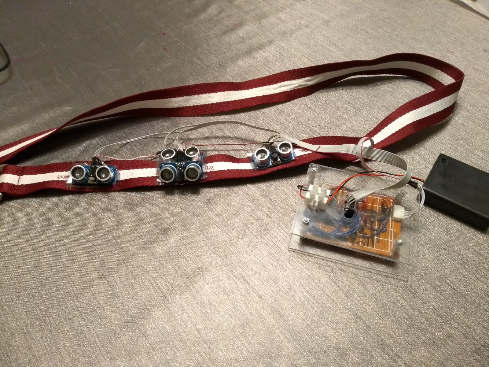
Total wearable
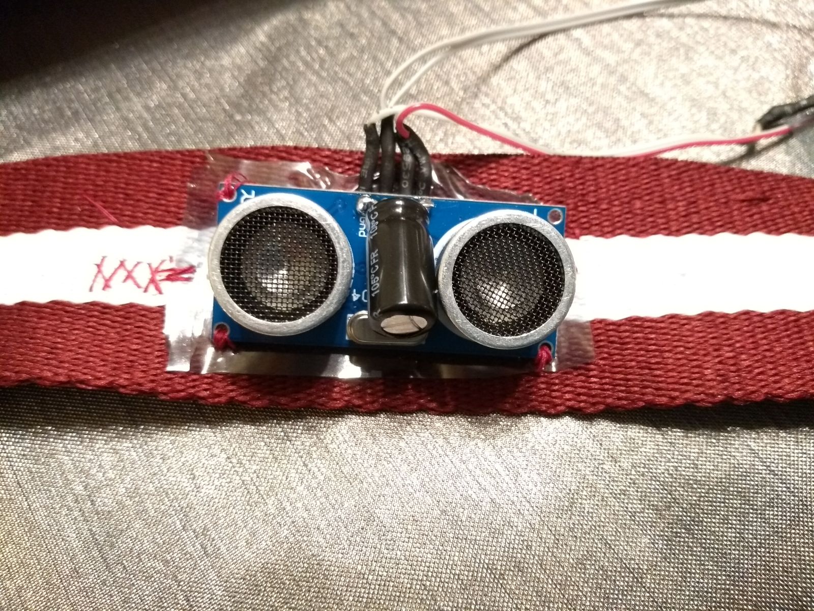
Distance sensor
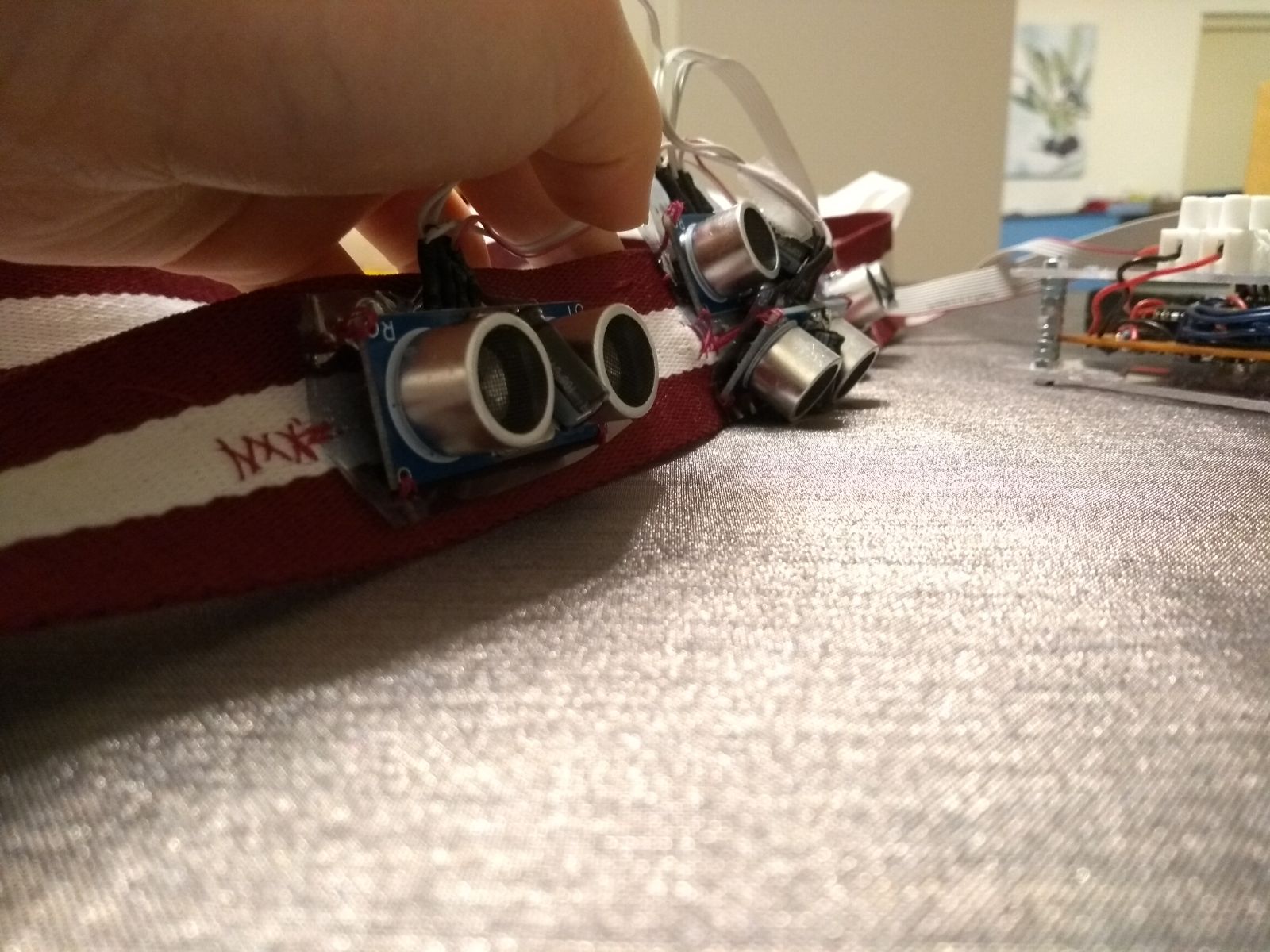
Distance sensors in several angles
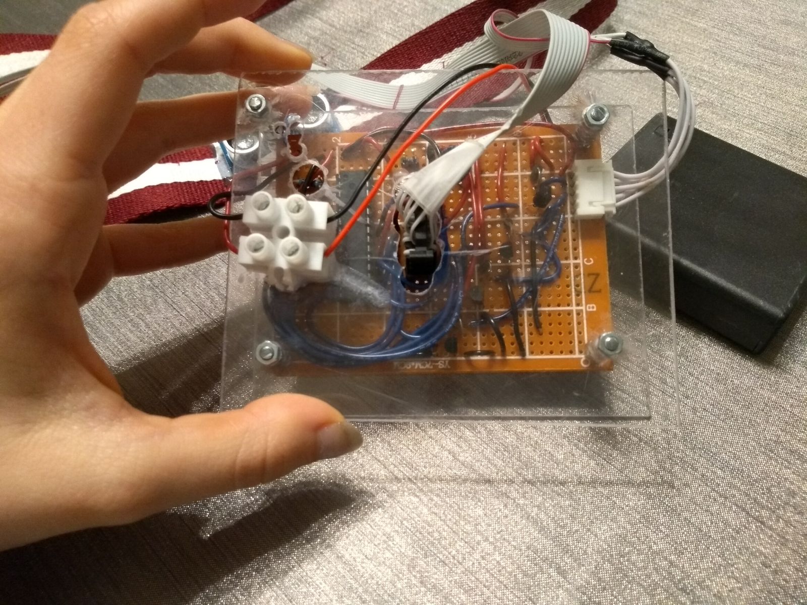
Technology
Arduino
Vibration motor
Mounted vibration motor
User wearing the wearable


Task division
| Week | Task | Person |
|---|---|---|
| 1 | Literature study | Everyone |
| Make planning | Everyone | |
| Determining roles | Everyone | |
| Making requirements | Everyone | |
| Writing problem statement | Evianne | |
| 2 | Determining a concrete problem | Everyone |
| Invent a solution to the concrete problem | Everyone | |
| Evaluate if the solution is user friendly and can be introduced to blind people | Everyone | |
| 3 | Update the overall planning | Evianne |
| Defining what problems can occur for blind people | Everyone | |
| Thinking about the scenario | Everyone | |
| Evaluate if the solutions are user friendly | Eline | |
| 4 | Literature study about the new problem | Tom |
| Defining the requirements and specifications of the to be built prototype | Evianne | |
| Think and write about design | Evianne | |
| Update wiki | Evianne | |
| Making a planning for each member | Tom & Evianne | |
| Think of technologies that should be used | Stefan & Tom | |
| Thinking about and writing the scenario | Bruno | |
| Thinking and writing about the feedback system | Bruno | |
| 5 | Define more specific requirements | Everyone |
| Make design of the belt | Everyone | |
| Write about the design | Eline | |
| Programming | Stefan | |
| Update wiki | Evianne | |
| Calculate angles and range sensors | Tom & Eline | |
| 6 | Start assembling the circuit | Stefan & Tom & Eline |
| Attaching the sensors | Eline | |
| Design for usability testing | Eline | |
| Calculating energy consumption | Stefan & Bruno | |
| Programming | Stefan | |
| Update Wiki | Bruno & Evianne & Tom | |
| Testing the preferables | Bruno & Evianne & Tom | |
| Writing the results of the tests | Bruno & Evianne | |
| Writing about sensor range | Tom | |
| 7 | Asemble the wearable | Tom & Eline & Stefan |
| Make a presentation | Evianne & Bruno | |
| Clean up the wiki | Evianne & Bruno | |
| Place pictures on wiki | Evianne |
Literature
[1] Aktar, T., Chen, J., Ettelaie, R., Holmes, M., & Henson, B. (2017). Human roughness perception and possible factors effecting roughness sensation. Journal of Texture Studies, 48(3), 181–192. http://doi.org/10.1111/jtxs.12245
[2] Alonso-Ríos, D., Vázquez-García, A., Mosqueira-Rey, E., & Moret-Bonillo, V. (2009). Usability: A Critical Analysis and a Taxonomy. International Journal of Human-Computer Interaction, 19. Retrieved from https://canvas.tue.nl/courses/2520/files/424795?module_item_id=31395
[3] Benniu, Z., Junqian, Z., Kaihong, Z., & Zhixiang, Z. (2007). A non-contact proximity sensor with low frequency electromagnetic field. Sensors and Actuators A: Physical, 135(1), 162–168. http://doi.org/10.1016/J.SNA.2006.06.068
[4] Brabyn, J. A. (1982). New Developments in Mobility and Orientation Aids for the Blind. IEEE TRANSACTIONS ON BIOMEDICAL ENGINEERING, (4). Retrieved from http://citeseerx.ist.psu.edu/viewdoc/download?doi=10.1.1.476.159&rep=rep1&type=pdf
[5] Filipe, V., Fernandes, F., Fernandes, H., & Sousa, A. (2012). Blind Navigation Support System based on Microsoft Kinect. Procedia Computer Science, 14, 94–101. http://doi.org/10.1016/J.PROCS.2012.10.011
[6] Ghiani, G., Leporini, B., & Paternò, F. (2009). Tactile Feedback to Aid Blind Users of Mobile Guides. Retrieved from http://giove.isti.cnr.it/attachments/publications/2008-A2-115.pdf
[7] Giudice, N. A., & Legge, G. E. (2008). Blind Navigation and the Role of Technology (pp. 479–500). http://doi.org/10.1002/9780470379424.ch25
[8] Holland, R. A., Thorup, K., Vonhof, M. J., Cochran, W. W., & Wikelski, M. (2006). Bat orientation using Earth’s magnetic field. Nature, 444(7120), 702–702. http://doi.org/10.1038/444702a
[9] Hong-Shik, K., & Jong-Suk, C. (2008). Advanced indoor localization using ultrasonic sensor and digital compass. COEX, Seoul, Korea. Retrieved from https://drive.google.com/drive/my-drive
[10] Jackson, M. R., Parkin, R. M., & Tao, B. (2001). A FM-CW radar proximity sensor for use in mechatronic products. Mechatronics, 11(2), 119–130. http://doi.org/10.1016/S0957-4158(99)00087-2
[11] Justesen, D. R., Adair, E. R., Stevens, J. C., & Bruce-Wolfe, V. (1982). A comparative study of human sensory thresholds: 2450-MHz microwaves vs far-infrared radiation. Bioelectromagnetics, 3(1), 117–25. Retrieved from http://www.ncbi.nlm.nih.gov/pubmed/7082383
[12] Kay, L. (1964). An ultrasonic sensing probe as a mobility aid for the blind. Ultrasonics, 2(2), 53–59. http://doi.org/10.1016/0041-624X(64)90382-8
[13] Lacey, G., & Dawson-Howe, K. M. (1998). The application of robotics to a mobility aid for the elderly blind. Robotics and Autonomous Systems, 23(4), 245–252. http://doi.org/10.1016/S0921-8890(98)00011-6
[14] Lee, Y., & Hamilton, M. F. (1988). A parametric array for use as an ultrasonic proximity sensor in air. The Journal of the Acoustical Society of America, 84(S1), S8–S8. http://doi.org/10.1121/1.2026546
[15] Lewis, J. R. (2012). Usability Testing. In G. Salvendy (Ed.), Handbook Human Factors Ergonomics (4th ed., pp. 1267–1312). Boca Raton, Florida. Retrieved from https://canvas.tue.nl/courses/2520/files/422231?module_item_id=31386
[16] Marcu, C., Lazea, G., Bordencea, D., Lupea, D., & Valean, H. (2013). Robot orientation control using digital compasses.pdf - Lumin PDF. Cluj-Napoca, Cluj, Romania. Retrieved from https://app.luminpdf.com/viewer/QhzEZo4ojPB7ThLf9
[17] Schlereth, T., Magerl, W., & Treede, R.-D. (2001). Spatial discrimination thresholds for pain and touch in human hairy skin. Pain, 92(1–2), 187–194. http://doi.org/10.1016/S0304-3959(00)00484-X
[18] Seraji, H., Steele, R., & Iviev, R. (1996). Sensor-based collision avoidance: Theory and experiments. Journal of Robotic Systems, 13(9), 571–586. http://doi.org/10.1002/(SICI)1097-4563(199609)13:9<571::AID-ROB2>3.0.CO;2-J
[19] Shaocheng, Q., ShaNi, Lili, N., & Wentong, L. (2011). Design of Three Axis Fluxgate Digital Magnetic Compass.pdf - Lumin PDF. Shanghai, China. Retrieved from https://app.luminpdf.com/viewer/B3LmcNjeMirMGQLML
[20] Shingchern, D. Y., & Yi-Ta, W. (2017). Using Digital Compass Function in Smartphone for Head-Tracking to Reproduce Virtual Sound Field with Headphones - Lumin PDF. Taipei, Taiwan. Retrieved from https://app.luminpdf.com/viewer/nL2aPdR8YXDQB2Lvn
[21] Story, M. F., Mueller, J. L., & Mace, R. L. (1998a). The Principles of Universal Design and Their Application. In The Universal Design File: Designing for People of All Ages and Abilities. (pp. 31–84). Retrieved from https://files.eric.ed.gov/fulltext/ED460554.pdf
[22] Story, M. F., Mueller, J. L., & Mace, R. L. (1998b). Understanding the Spectrum of Human Abilities. In The Universal Design File: Designing for People of All Ages and Abilities. (pp. 15–30). Retrieved from https://files.eric.ed.gov/fulltext/ED460554.pdf
[23] When close is good enough - ProQuest. (1995). Retrieved from https://search.proquest.com/docview/217152713?OpenUrlRefId=info:xri/sid:wcdiscovery&accountid=27128
[24] Yuan, D., & Manduchi, R. (2004). A Tool for Range Sensing and Environment Discovery for the Blind. Retrieved from https://users.soe.ucsc.edu/~manduchi/papers/DanPaperV3.pdf
[25] Zhang, L., & Chang, J. (2011). Development and error compensation of a low-cost digital compass for MUAV applications.pdf - Lumin PDF. Hohhot, China. Retrieved from https://app.luminpdf.com/viewer/9XdHqSGPtTPycCiXu
[26] Park, K. T., & Toda, M. (1993). U.S. Patent No. US5483501A. Washington, DC: U.S. Patent and Trademark Office.
[27] Widmann, F. (1993). U.S. Patent No. US5602542A. Washington, DC: U.S. Patent and Trademark Office.
[28] Miller, B. A., & Pitton, D. (1986). U.S. Patent No. US4694295A. Washington, DC: U.S. Patent and Trademark Office.