Opening
The opening is the first stage in the package delivery process, here the package is received from the drone.
To read more about how the designing of this stage went please view: Designing the Opening Component.
Design
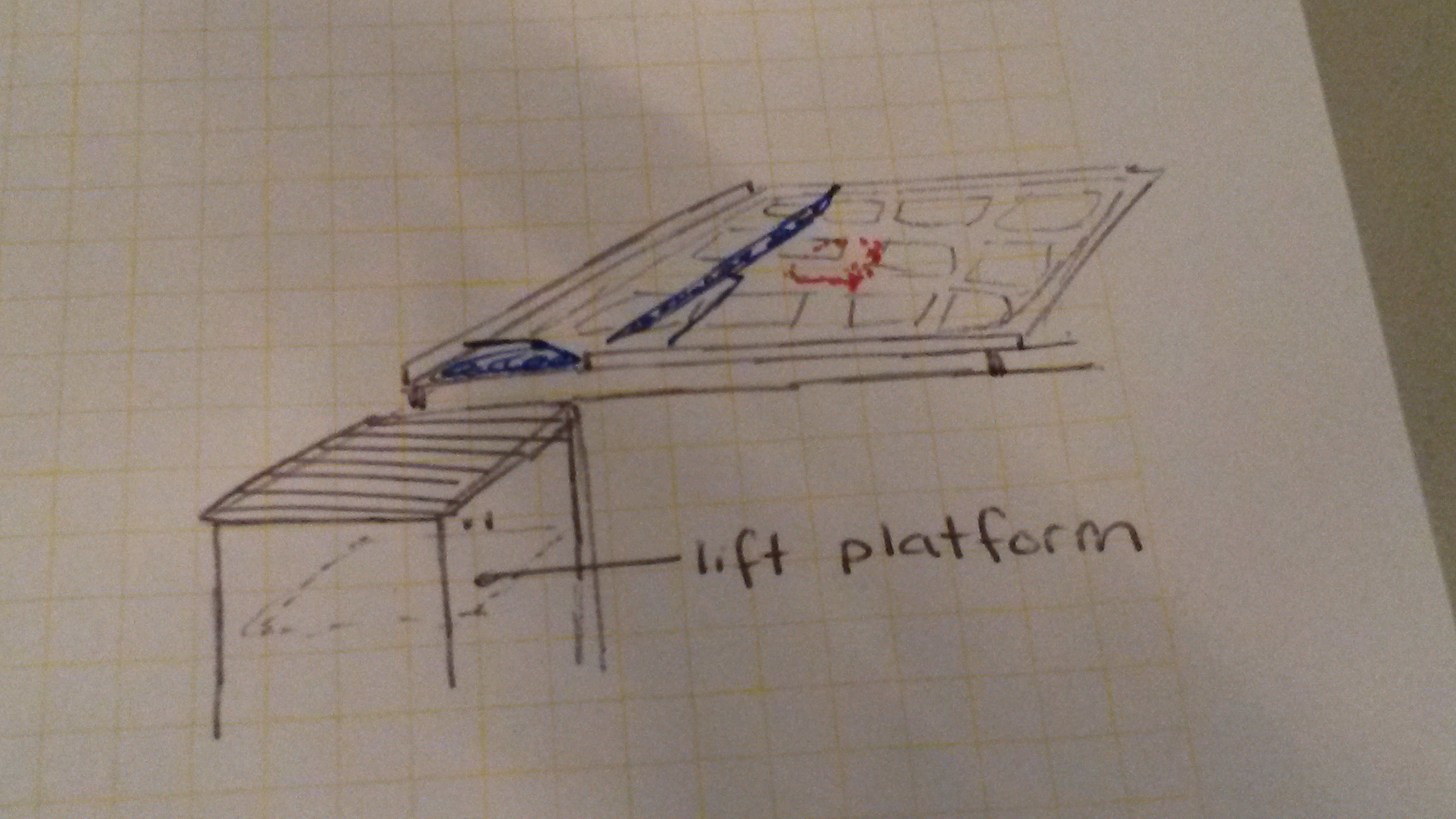
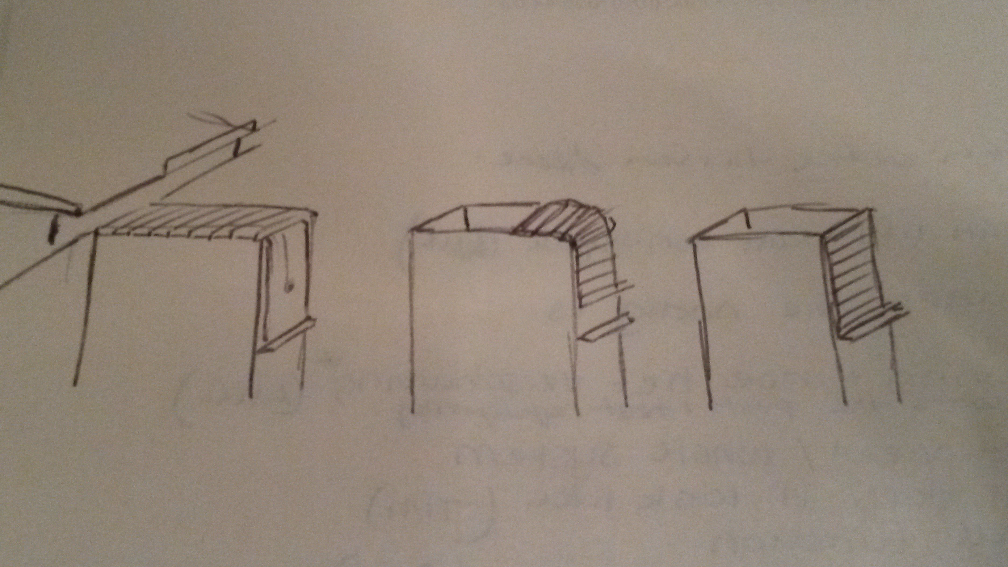
Isometric Sketch
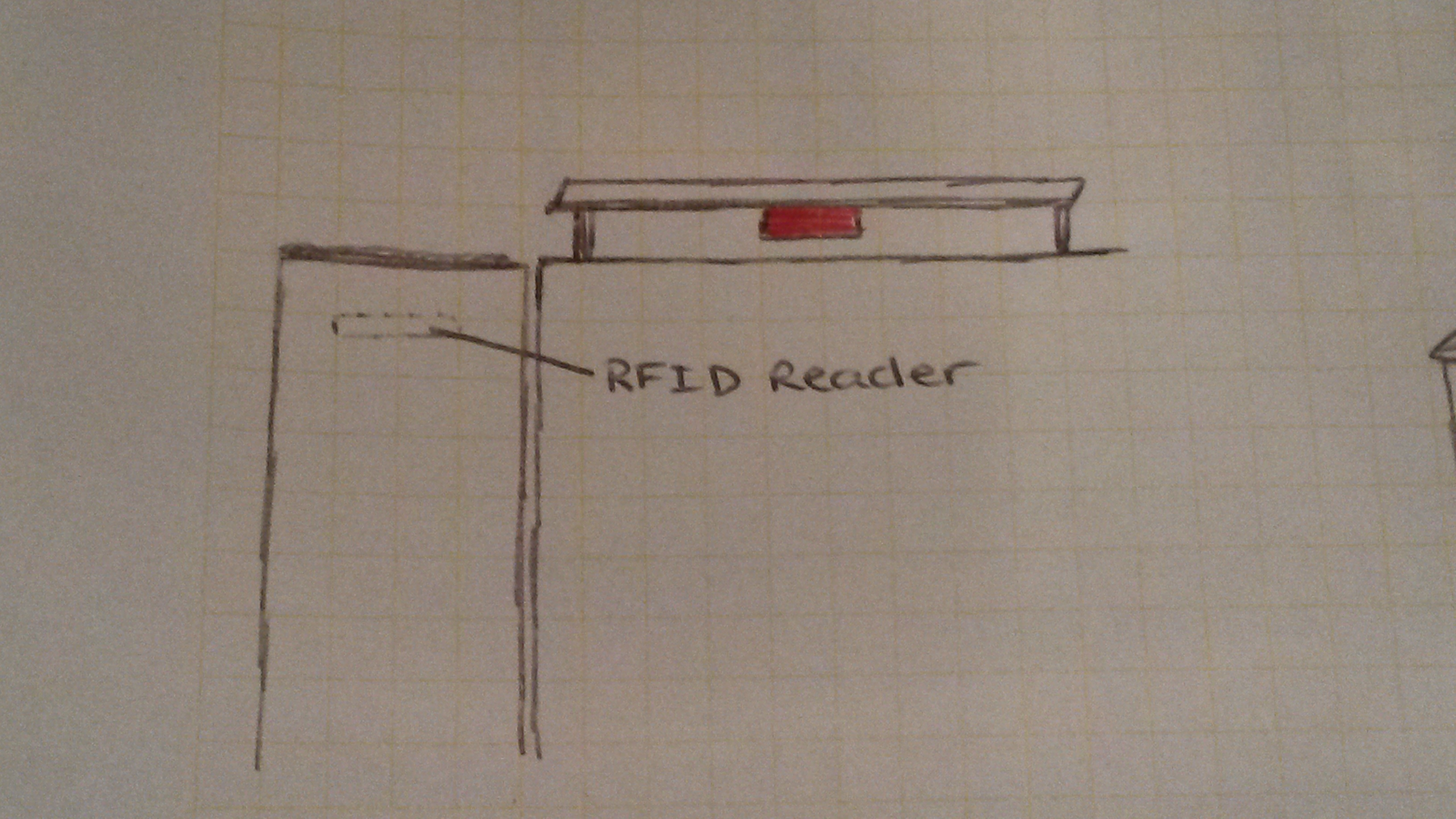
Side view
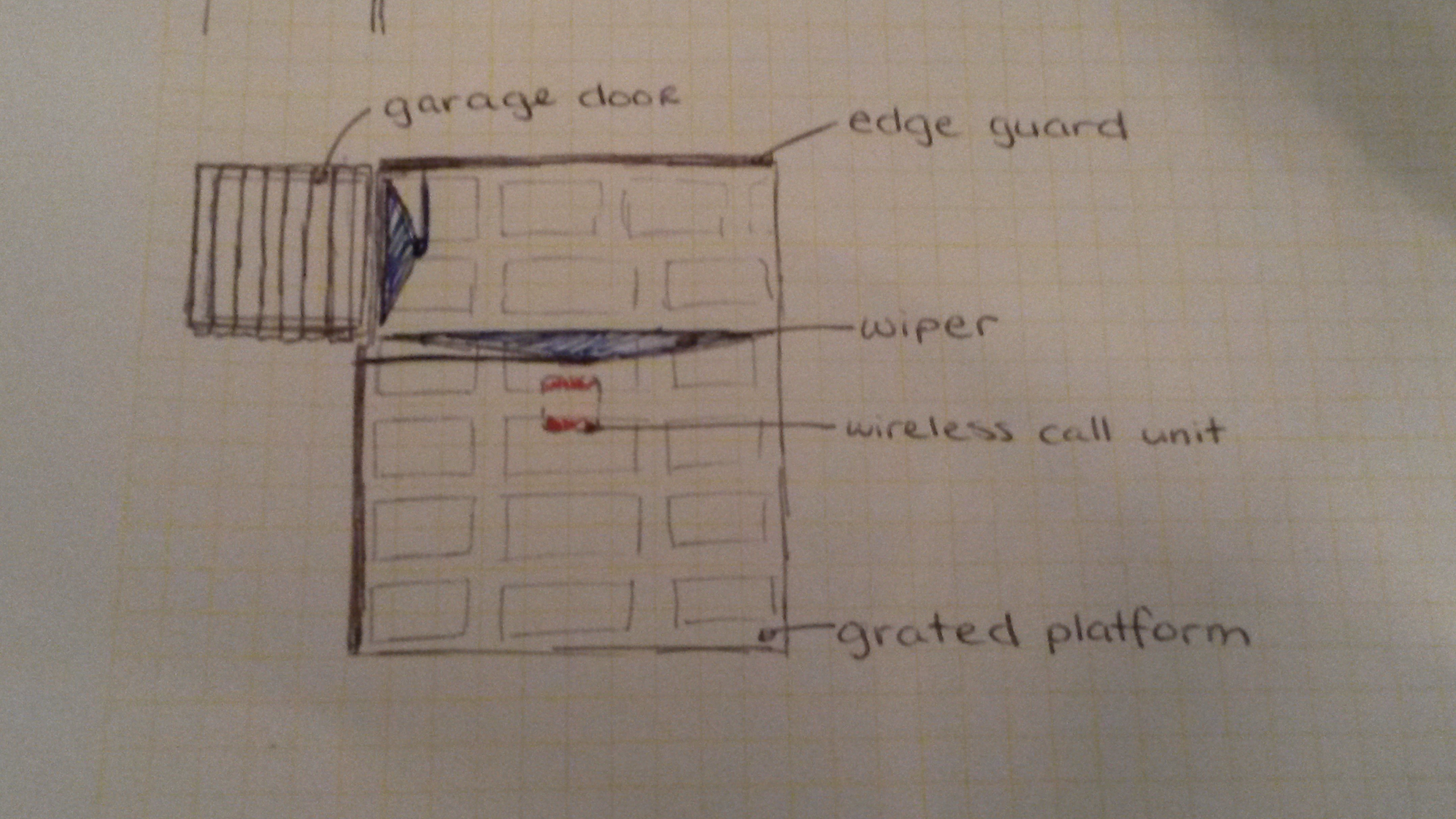
Top View
Garage door component


How It Works
KS-OpeningP7-30-09
KS-OpeningP8-1-10
KS-OpeningP9-2-10


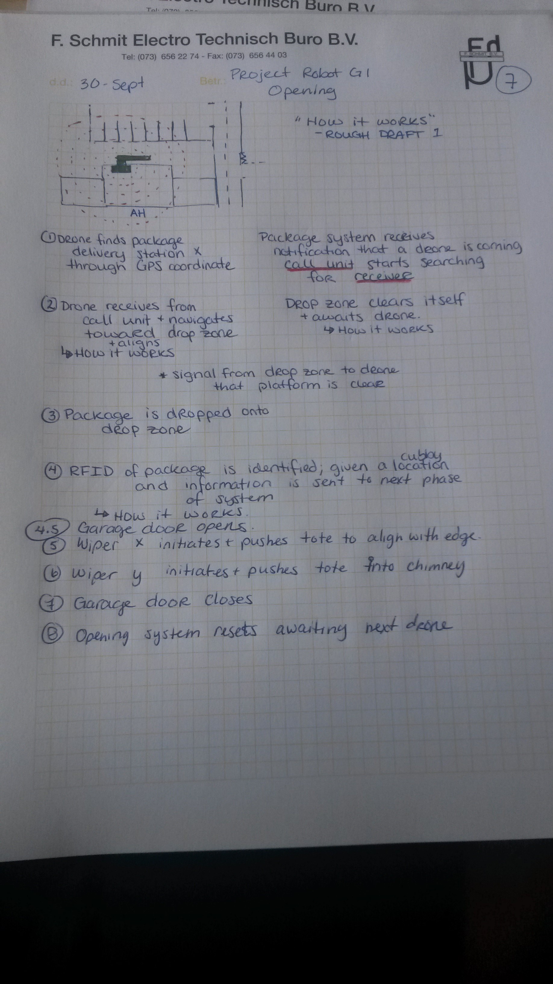
Basic Outline on "How it functions"
- Drone Finds package delivery station X through GPS coordinate.
- Drone receives signal from call unit & navigates toward the drop zone
- Dropzone "cleans itself"
- Signal from Drop Zone to Drone to say that platform is clear
- Package is dropped onto dropzone
- Garage Door opens
- Wiper x initiates and pushes tote to align with edge
- Wiper y initiates and pushes tote into chimney
- RFID of package is identified; coupled on a cubby location and information is sent to the next phase of system
- Garage door closes
- Opening system resets awaiting next drone.
In Depth - How Opening Works
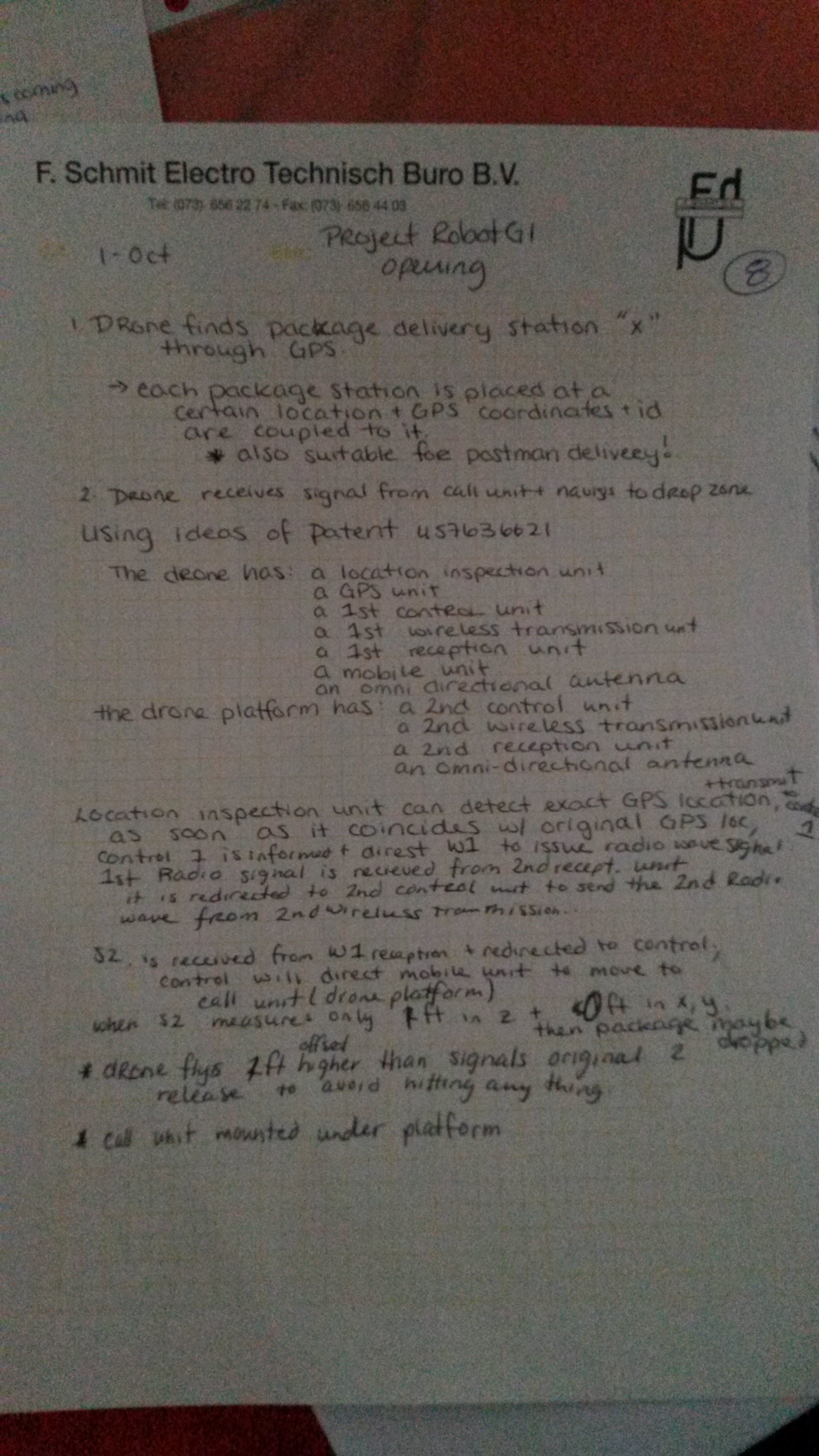
1. Finding Delivery Station
Each package pick-up station is placed at a certain location ( be it a supermarkt, in the center of a neighboorhood etc.), GPS location and Identification numbers are coupled to it.
The drone, which has GPS navigation, can be input with the pick-up location ID and then navigate towards the GPS location.
This portion uses the system described in Patent US7636621.
It has been tweaked to suite the purposes of this design.
Description of how it works in the patent:

"Please refer to FIG. 2, which is a functional block diagram of an autonomous mobile device with its changing station according to the present invention. In FIG. 2, the autonomous mobile device 2 is comprises of: a capacity inspection unit 21, a power unit 22, a first control unit 23, a first wireless transmission unit 24, a first reception unit 25, a mobile unit 26 and a first charging interface 27; and the call unit 3 is comprised of: a second control unit 31, a second wireless transmission unit 32, a second wireless reception unit 33, and a second charging interface 34. The capacity inspection unit 21 is capable of detecting the power of the power unit 22 while transmitting the result of the inspection to the first control unit 23. As soon as the detection of the capacity inspection unit 21 shows that the power of the power unit 22 is too low and the first control unit 23 is informed of the detection result, the first control unit 23 will direct the first wireless transmission unit 24 to issue a first radio wave signal S1. As the first radio wave signal S1 is received by the second wireless reception unit 33, it is redirected to the second control unit 31 for enabling the same to command the second wireless transmission unit 32 to issue a second radio wave signal 52. Thereafter, as soon as the second radio wave signal S2 is received by the first wireless reception unit 25 and is redirected to the first control unit 23, the first control unit 23 will direct the mobile unit 26 to move toward the call unit 3. Therefore, as soon as the connection port P1 of the first charging interface 27 is in contact with the connection port P2 of the second charging interface 34 and by the cooperative operation of the first and the second control units 23, 31, the autonomous mobile device 2 is charged by the call unit 3." [1]
Tweaks made:
The capacity inspection unit 21 becomes a location inspection unit 21 and there will be no charging interface.
The scenario would be as follows:
"As soon as the detection of the Location inspection unit 21 shows that the current GPS location is the same as the destination GPS location and the first control unit 23 is informed of the detection result, the first control unit 23 will direct the first wireless transmission unit 24 to issue a first radio wave signal S1. As the first radio wave signal S1 is received by the second wireless reception unit 33, it is redirected to the second control unit 31 for enabling the same to command the second wireless transmission unit 32 to issue a second radio wave signal 52. Thereafter, as soon as the second radio wave signal S2 is received by the first wireless reception unit 25 and is redirected to the first control unit 23, the first control unit 23 will direct the mobile unit 26 to move toward the call unit 3. Therefore, as soon as the location inspection unit indicated 0 offset in the x and y direction and 1ft positive offset in the z direction from S2, hovering directly above call unit, the drone maintains location, sends alignment signal S3 and awaits next signal."
N.B Calculation is performed to make the movements of the drone to the call unit. In these calculations there should be a 1ft offset in the positive z direction performed first to ensure that the drone hovers above the platform and not under it.
Also making the platform and its mechanisms out of plastic would prevent interference with the radio signaling process that occurs above.
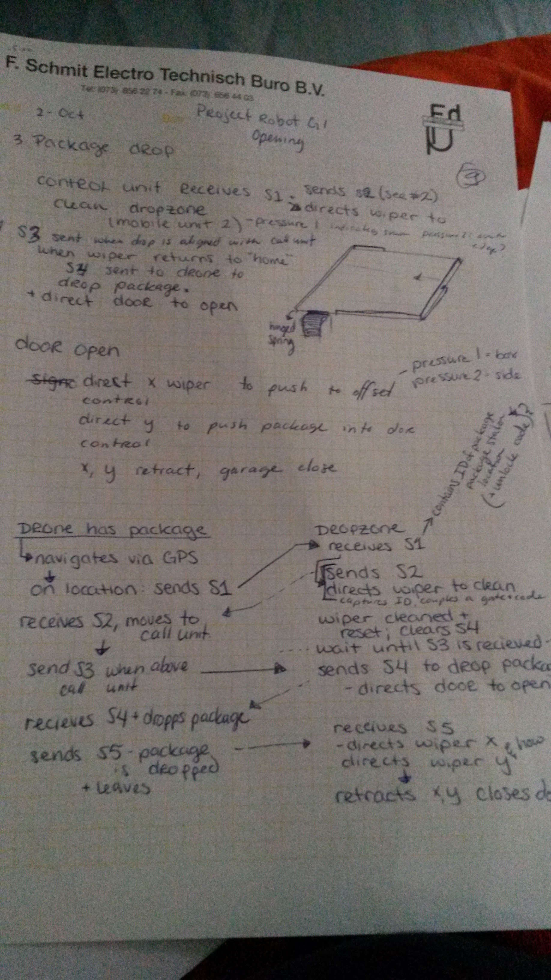
3. Package Drop & Identification
To add on to the scenario sketched above we need a means to identify the parcel & give it a cubby location. This shall be done by RFID.
Each delivery tote shall be coupled with a re-writable battery-assisted passive RFID tag and each drone shall have a battery-assisted passive RFID tag. This kind of tag has a small battery that is activated when in the presence of an RFID reader, which shall be located on the drone platform. The reason to use this specific kind of tag is that is it can be given a specific identification which is re-writable and also the tag becomes active when in the range of a reader[2]. Imagine similar use as animal identification tags or EZ-Passes for toll ways.
Mounted in the chimney under the garage door, and RFID reader will be located. It continually transmits an encoded radio signal that will eventually interrogate the tags (RFID1). The RFID tags of the drone and tote receive the signal and responds with its ID and other information coupled to the tag(RFID2 & RFID3). The reader receives the signals and sends the information to the pick-up systems database where it couples the tote ID(RFID2) to a cubby number which is used again in a later stage of the pick-up system and designates the drone ID(RFID3) to the call unit queue for drone delivery. Mounting the RFID readers in strategic points along the package pick-up station helps keep track of the location of packages within the system, has also been shown to help keep inventory up-to-date in distribution centers [3].
N.B. Placing the RFID signals on a different frequency would assist in minimizing interference.
4. Package To Chimney
The activation of the wipers & door mechanisms utilized by the dropzone are coupled to the initial signals sent and received from the wireless unit used for navigation (explained above).
Signal S1 from the drone activated the system to start sending S2 the navigation signal while also directing the wipers to clear off the platform. This helps in limiting debris and snow from getting into the system. Both Wiper x and Wiper y move across to their "start positions" near the edges of the platform. The control center is notified that the dropzone is cleared. During this process, Alignment signal S3 sent from the drone, may be received; it informs the pick-up system that a drone is in place for delivery. Once the clearance of the dropzone is confirmed the unit sends drop signal S4 to the drone. Then the drone receives the signal, sends S5 - package signal and the drone drops the package and leaves.
Now starts phase 2 - getting the package to the chimney. Signal S5 is received by the drone platform and a delayed control action is sent to the wipers. The garage door mechanism slides open awaiting the package. After 10 seconds delay, wiper X moves first to align the package with the chimney. Via a pressure plate located on the wiper X, alignment is detected when the package comes in contact with the guard and increases pressure. Then wiper y pushes and the package falls into the chimney onto a loading platform located <1ft below the opening. Then both wipers go back the their pre-package state and the garage door closes and a signal is sent to the control box that the system has been cleared for another package.
Multiple Drone Deliveries?
If multiple drones come to deliver to the same system simultaneously, there exists a queue. Each individual drone has their own RFID which can be identified by the RFID reader when the drone sends their signal 1(S1) for location coordinates. Once S1 is received by the call unit and the RFID tag is identified and stored, it sends signal 2 (s2) with special ID coding so that the individual drone will know the signal is for it upon receive. Other drones could also send a signal 1, which the call unit will then place the ID's in a queue and allow the system to perform its further work. The other drones in the area could also receive signal 2, but the RFID coding allows individualized action.
Simultaneous and speedy transactions can occur with RFIDs at check-out of certain stores[4]. This type of system could be manipulated to make a queue type system as stated above.
Requirements
Green background color indicates that they have been fulfilled. No background color indicates that the requirement is either external or not considered/tested while creating this current concept.
| Functional | Process | External |
|---|---|---|
| The component should be able to accept a package from a drone. | The component should be able to identify the package & designate a cubby location. | The delivery drones must be capable of moving to an exact location in x, y and z direction. |
| The component should be able to get the package to the next phase of delivery. | The component should complete package retrieval within 30 seconds. | The delivery drones must have a Wifi Signal receiver to retrieve platform location information |
| The component should have a way to handle debris & weather complications. | The component should communicate with the delivery drone to provide location information. | The delivery drones should be able to calculate approach and positioning |
| The component should be able to report malfunction. | The component should know when a package is on the platform and is clear to proceed. |
BACK: Concepts Chosen
NEXT: Chimney
References
- ↑ Industrial Technology Research Institute-Taiwan. (2009). Path Guidance method for autonomous mobile device. <http://www.google.com/patents/US7636621>
- ↑ N.A. (2007).Passive RFID Enters Fast Lane in Transportation and Logistics. Intelleflex Corporation.<http://www.intelleflex.com/pdf/solutionsbrief.transportationandlogistics.pdf>
- ↑ Angeles, R. (2005). RFID technologies: supply-chain applications and implementation issues. Information Systems Management, 22(1), 51-65.
- ↑ Vieru, T. (2010). Advanced RFID Chips Could Make Queues History. Softpedia. <http://news.softpedia.com/news/Advanced-RFID-Chips-Could-Make-Queues-History-137951.shtml>