Mobile Robot Control 2020 Group 6
Group Members
Students (name, id nr):
Joep Selten, 0988169
Emre Deniz, 0967631
Aris van Ieperen, 0898423
Stan van Boheemen, 0958907
Bram Schroeders, 1389378
Pim Scheers, 0906764
Logs
This section will contain information regarding the group meetings
| Date/Time | Roles | Summary | Downloads | |
|---|---|---|---|---|
| Meeting 1 | Wednesday 29 April, 13:30 | Chairman: Aris Minute-taker: Emre |
Introductionary meeting, where we properly introduced ourselves. Discussed in general what is expected in the Design Document. Brainstormed of solutions for the Escape Room challenge. Set up division of tasks (Software Exploration/Design Document). | Minutes |
| Meeting 2 | Wednesday 6 May, 11:30 | Chairman: Emre Minute-taker: Stan |
Discussing our V1 of the Design Document with Wouter. Devised a plan of attack of the escape room competition and roughly divided the workload into two parts (Perception + world model and Strategy + Control). | Minutes |
| Meeting 3 | Monday 11 May, 11:00 | Chairman: Stan Minute-taker: Joep |
Discussing what needs to be finished for the Escape Room challenge. | Minutes |
| Meeting 4 | Friday 15 May, 9:00 | Chairman: Joep Minute-taker: Bram |
Evaluating the escaperoom challenge and the groupwork so far. Made agreements to improve the further workflow of the project. | Minutes |
| Meeting 5 | Wednesday 20 May, 11:00 | Chairman: Bram Minute-taker: Pim |
Discussing towards an approach for the hospital challenge. First FSM is introduced and localization/visualization ideas are discussed. | Minutes |
| Meeting 6 | (Date), Time | Chairman: Pim Minute-taker: Aris |
(Summary goes here) | (Downloadable minutes goes here) |
Design Document
The design document, which describes the design requirements, specification, components, functions and interfaces can be seen here.
Escape Room Challenge
The escape room challenge required the PICO robot to escape a room with limited prior knowledge of the environment. The information architecture of the embedded software has been designed in the design document, the main components being: Perception, World Model, Monitor & Strategy and Control. The world model has been visualized using openCV which is available via ros.
Perception
The objective of the escape room challenge is finding and driving out of the exit. To be able to achieve this, the robot should recognize the exit and find its location, which is the main objective concerning perception. For this challenge, the features of the room are only stored locally. The robot tries to recognize the exit, where after the location w.r.t. the robot is determined. First of all, unusable data points of the LRF sensor have been filtered out. A line detection and an edge detection functionality has been implemented in order detect the walls of the room in local coordinates. This way, at each time step, the begin point, the end point, and the nearest point of the walls can be observed by PICO. The functions work in the following manner:
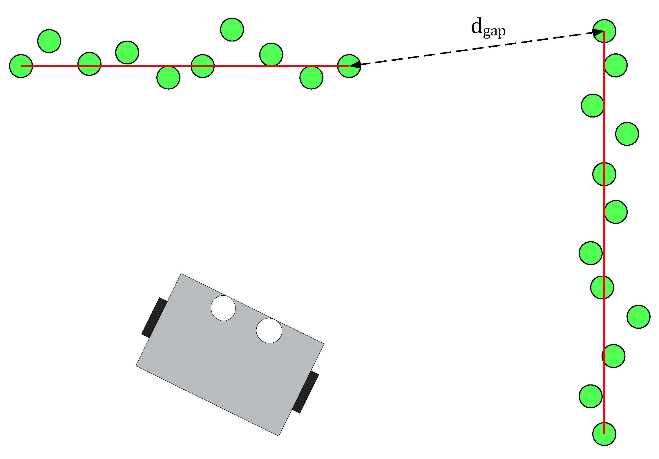
- Line detection: the LRF data consist of 1000 points with each a range value, which is the absolute distance to PICO. The line detection function loops over the data and calculates the absolute distance between two neighboring data points. When the distance exceeds the value dgap, the line-segment can be separated.
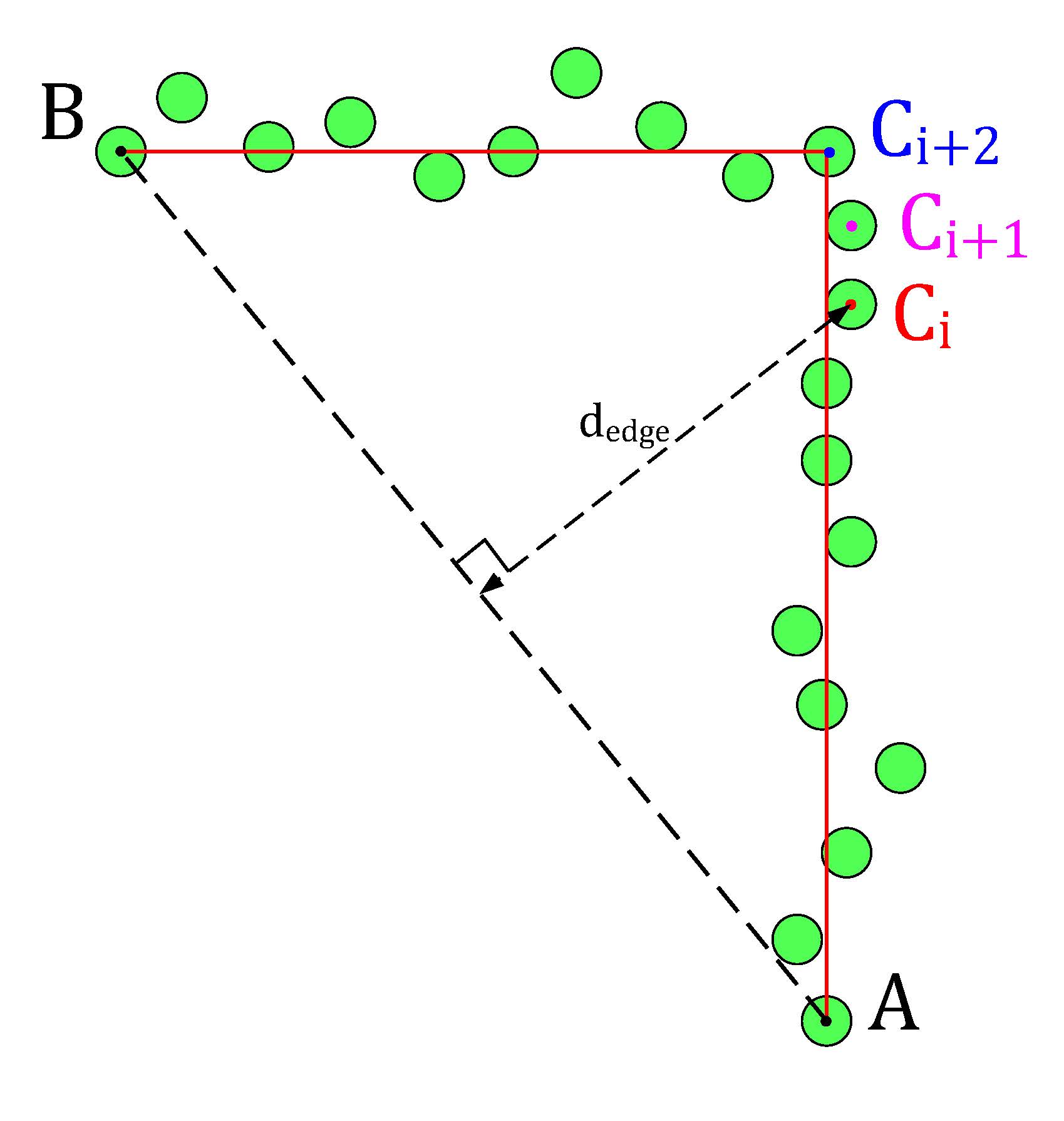
- Edge detection: the line detection algorithm only detects if data points have a large distance relative to each other. The edge detection function detects if the line-segments (which result from the line detection) contain edges. The basic idea of the implemented algorithm can be seen in the figure below. The line segment in that figure has a starting data point A and an end point B. A virtual line, AB, is the drawn from point A to B. Finally the distance from the data points Ci, which lie inside the segment, to the virtual line AB is calculated, dedge. The largest value dedge can be considered an edge.
Line detection algorithm of the PICO robot.
Edge detection algorithm of the PICO robot.


With the ability to observe and locate walls, gaps can be easily detected. basic idea of this gap detection algorithm is that the robot looks for large distances between subsequent lines. The threshold for this difference can be tuned in order to set the minimum gap size. The world model not only stores the local coordinates of gaps, but it also stores the exit walls. The function gapDetect in the class Perception is responsible for storing both the gaps and exit walls in the world model. The visualization beneath shows the localization of a gap in a room. The bright red circle represents the set-point to which PICO will drive towards. This set-point contains a small adjustable margin which prevents collisions with nearby walls.

Some additional features were added, which adds robustness to the line/edge and the gap detection:
- Adjustable parameter MIN_LINE_LENGTH which sets the minimum amount of data points for which we can define a line. With this implementation stray data points will not be perceived as lines.
- Adjustable parameter MIN_GAP_SIZE, which sets the minimum gap size. When the gap size between two lines is lower than this value, everything inside that gap is ignored.
- Adjustable parameter GAP_MARGIN, which as previously mentioned adds a margin to the gap set-point.
With these features, a rather robust perception component has been developed. The resulting performance can be seen in the recording below. The detected lines and gap have been visualized. Small gaps and lines which are present in this custom map are ignored.

World Model
The world in the Escape room challange, stored the following features:
- segments: this member variable in the world model class contains every line segment in a vector. A Line struct has been added which stores the beginning position and end position index and coordinates. The coordinates can be stored with a Vec2 struct.
- gaps: this member variable in the world model class contains the perceived gaps in a vector. A Gap struct has been implemented which stores the gap coordinates (Coords), the gap coordinates including a margin (MCoords) and the gap size.
- exit_walls: this memeber variable contains the 2 exit walls in a vector. These walls are stored as the before mentioned Line struct.
Keep in mind that these features are being renewed constantly during the operation of PICO.
Monitor and strategy
The goal of Monitor is to map the current situation into discrete states using information of the environment. For the escaperoom four different situations are checked, namely whether a wall, a gap, a corner or an exitwall is found in Perception.
Strategy controls a Finite State Machine, shown in the figure below, that is used to determine which action Control should take. The discrete states from Monitor are used for the guards of this final state machine. When the state machine is in the state FindWall, Control get the objective to move untill a wall is detected. In the state FollowWall Control follows the wall which is the closest to the robot. From FollowWall it can either go to GoToGap, when a gap is detected, or to CrossToWall. In CrossToWall the objective for Control is to follow the wall that is perpendicular to the wall it is currently following. This way the corner is cut-off. When the gap is detected the robot directly goes to this gap and when it recognizes the finish it will drive to the finish.

Control
In control, a main functionality is to drive towards a target. Therefore the function "GoToPoint()" is created. This function allows the robot to drive towards a point in its local coordinates. The input is a vector which defines the point in local coordinates. Reference velocities are send towards the base in order to drive towards this point. The robot will not drive and only turn when the angle towards the point is too high, this angle is made into a tunable parameter.
For our strategy, it is necessary that PICO can follow a wall, hence a “FollowWall( )” function is created. The “FollowWall( )” function creates an input point (vector) for the “GoToPoint( )” function. To create this point two parameters are used. One for the distance from the wall to the destination point, and one for the distance from PICO to the destination point. Both are tunable parameters. With the use of some vector calculations this point is created in local coordinates. The benefit of this method is that drift is eliminated, since the point is updated each timestep. Also PICO will approach the wall in a smooth curve and the way this curve looks like is easy tuned by altering the parameters. The following figure presents this approach.

Validation
Challenge
On May 13th the escape room challenge was held, where the task was to exit a simple rectangular room through its one exit without any prior information about the room. We had prepared two branches of code, to allow ourselves to have a backup. With the software described in the previous sections, the first attempt showed behavior which was very close to the video below. Unfortunately, when the robot turned its back towards the wall it should be following, it got stuck in a loop which it could not escape. From the terminal we could read that the robot remained in a single state, called FollowWall. However, its reference direction did constantly change.

The code for the second attempt, which omitted the use of the states GoToGap and GoToFinish, made use of two states only, being FindWall and FollowWall. This meant that the issue we faced in the first attempt was still present in the new code, hence exactly the same behavior was observed.
During the interview, it was proposed by our representative that the issue was a result of the robot turning its back to the wall, meaning that the wall behind it is not entirely visible. In fact, because the robot can not see directly behind, the wall seems to be made out of two parts. During turning, the part of the wall which is closest to the robot is used in the FollowWall function changes, hence the reference point changes position. Then, with the new reference point the robot turns again, making the other section of the wall closest, causing the robot to turn back and enter a loop.
During testing with the room that was provided after the competition, a different root to our problems was concluded. As it turned out, the wall to the rear left of the robot almost vanishes when the robot is turning clockwise and its back is facing the wall, as can be seen in the left video above. This means that this wall no longer qualifies as a wall in the perception algorithm, hence it is not considered as a reference wall anymore. This means that the robot considers the wall to its left as its reference, meaning that it should turn counterclockwise again to start moving parallel to that. At that point, the wall below it passes over the threshold again, triggering once again clockwise movement towards the exit.
With this new observation about the reason the robot got stuck, which could essentially be reduced to the fact that the wall to be followed passed under the threshold, the first debugging step would be to lower this threshold. Reducing it from 50 to 20 points, allowed the robot to turn clockwise far enough, so that the portion of the wall towards the exit came closest and hence could be followed. This meant that the robot was able to drive towards the exit, and out of the escape room without any other issues, as can be seen in the video below. All in all, it turned out that the validation we had performed before the actual challenge missed this specific situation where the robot was in a corner and had to move more than 90 degrees towards the exit. As a result, we did not tune the threshold on the minimum amount of points in a wall well enough, which was actually the only change required to have the robot finish the escaperoom.
