Mobile Robot Control 2020 Group 4: Difference between revisions
| Line 73: | Line 73: | ||
# A corner that is seen from one side and inferred | # A corner that is seen from one side and inferred | ||
# The end of a wall’s observation caused by occlusion of PICO’s blind spot. | # The end of a wall’s observation caused by occlusion of PICO’s blind spot. | ||
[[File:PICO detected features 2.png|right|400 px]] | |||
=====Segmentation ===== | =====Segmentation ===== | ||
Revision as of 18:05, 7 June 2020
Group Members
| Name | Student Number | |
|---|---|---|
| M. Katzmann | 1396846 | m.katzmann@student.tue.nl |
| B. Kool | 1387391 | b.kool2@student.tue.nl |
| R.O.B. Stiemsma | 0852884 | r.o.b.stiemsma@student.tue.nl |
| A.S.H. Vinjarapu | 1502859 | a.s.h.vinjarapu@student.tue.nl |
| D. van Boven | 0780958 | d.v.boven@student.tue.nl |
| R. Konings | 1394819 | r.konings@student.tue.nl |
Escape Room Challenge
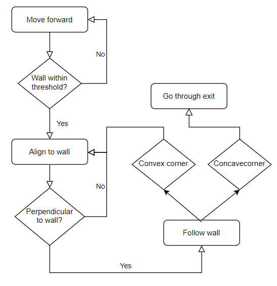
To safely get the PICO robot to the exit of the escape room, the strategy to implement a wall-follow algoritm is chosen. If the Algoritm is implemented succesfully it should be a safe and quick solution to the problem. The PICO will follow move to a wall, after which he will align perpendicular to the wall. When aligned to the wall, PICO will move left until it reaches either a wall or a gap. It will choose to rotate or drive into the gap accordingly. This algorithm is being chosen because by researching Escape Room project of previous years, this algorithm scored well, based on time and whether the PICO finished at all.
The wall-follow algorithm is divided into the following subparts:
Step 1: The PICO moves forward
- The PICO moves forward until it reaches a wall. The PICO will start at a random location inside the escame room. This means the robot can be anywhere inside the room. Thus, the first thing PICO does is move forward until it detects a wall getting closer. As the wall gets closer, the velocity of PICO decreases until it reaches a certain threshold from the wall, which means the PICO will stop moving.
Step 2: The PICO aligns to the wall
- When PICO reaches the wall and completely stops moving, PICO starts rotating. It will rotate until it is perpendicular to the wall. This is achieved by having PICO stop rotating once the the middle LFR sensor has the smallest value. Here, the rotational velocity also decreases when the distance to the end point decreases.
Step 3: The PICO follows the wall
- Once the PICO is perpendicular to the wall, it is ready to start following the wall. This is done by moving the PICO to the left until it detects a corner. If the PICO detects a convex corner, this means there is a corner approaching, and if the PICO detects a concave corner, this means there is a corridor approaching. The PICO will take the correct measures in the next step according to what it detects.
Step 4: The PICO makes choices according to what it detects
- If this corner is convex
- The PICO will align to the wall which is perpendicular to the previous wall. Wehn aligned correctly it will go back to step 3 and repeat the process.
- The PICO will align to the wall which is perpendicular to the previous wall. Wehn aligned correctly it will go back to step 3 and repeat the process.
- If this corner is concave
- The PICO drives a little further until the PICO is aligned to the exit. Once it is aligned to the corridor and feels safe enough to move, the PICO will move forward until the exit is reached.
- The PICO drives a little further until the PICO is aligned to the exit. Once it is aligned to the corridor and feels safe enough to move, the PICO will move forward until the exit is reached.
During the wall-follow algoritm, the PICO checks if it is too close to a wall and if it is well alligned at all times.
Escape room challenge results
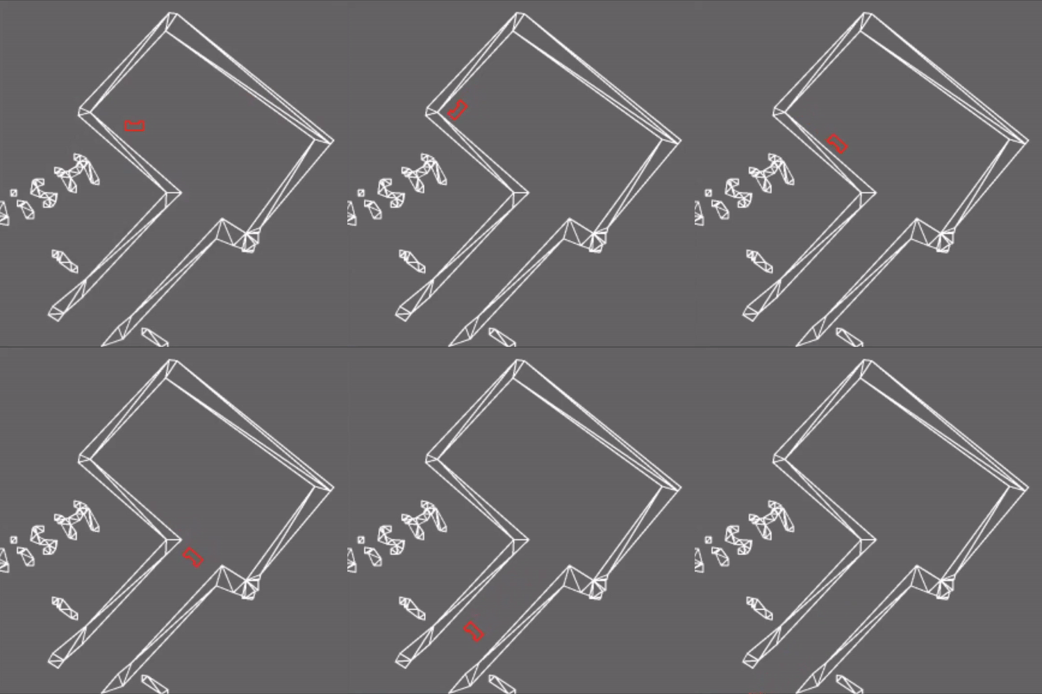
With the wall-following algorithm, the PICO achieved second place in the escape room challenge. The exit was reached within 27 seconds. The result of the challenge can be seen in the video. With the created algoritm, it can be seen that PICO firstly moves to the wall in front of him and stops when he is within the threshold range. Afther this, PICO perfectly aligns himself perpendicular to the wall, ready to move to the left. When moving to the left, first it encounters a convex wall, which means he rotates and aligns to the wall left of him. After the PICO is aligned to the new wall, it moves to the left until it encounters the corridor. Here, the PICO positions himself in front of the corridor. Once the PICO is positioned and feels it is safe enough to move, it drive through the corridor to the exit.
Hospital Challenge
[Under construction]
For the Hospital Challenge, the design of the algorithm is divided into four parts: interaction, supervisory, mapping and navigation. Each part has its own functionality and needs to work with the other parts. This functionality is explained below:
Interaction
These are all low-level interactions consisting mostly of calls to the IO API (which represents communication with PICO).
Supervisory
This section covers the governing control logic of the proposed system. The idea is that the supervisor makes choices, tunes parameters, and controls flow-of-command with in remaining code depending on its mode, and changes modes dynamically.
Mapping
Feature Recognition
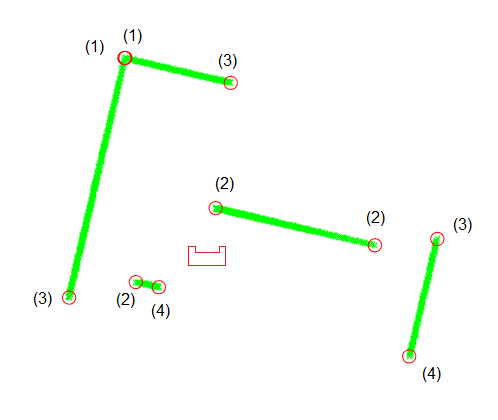
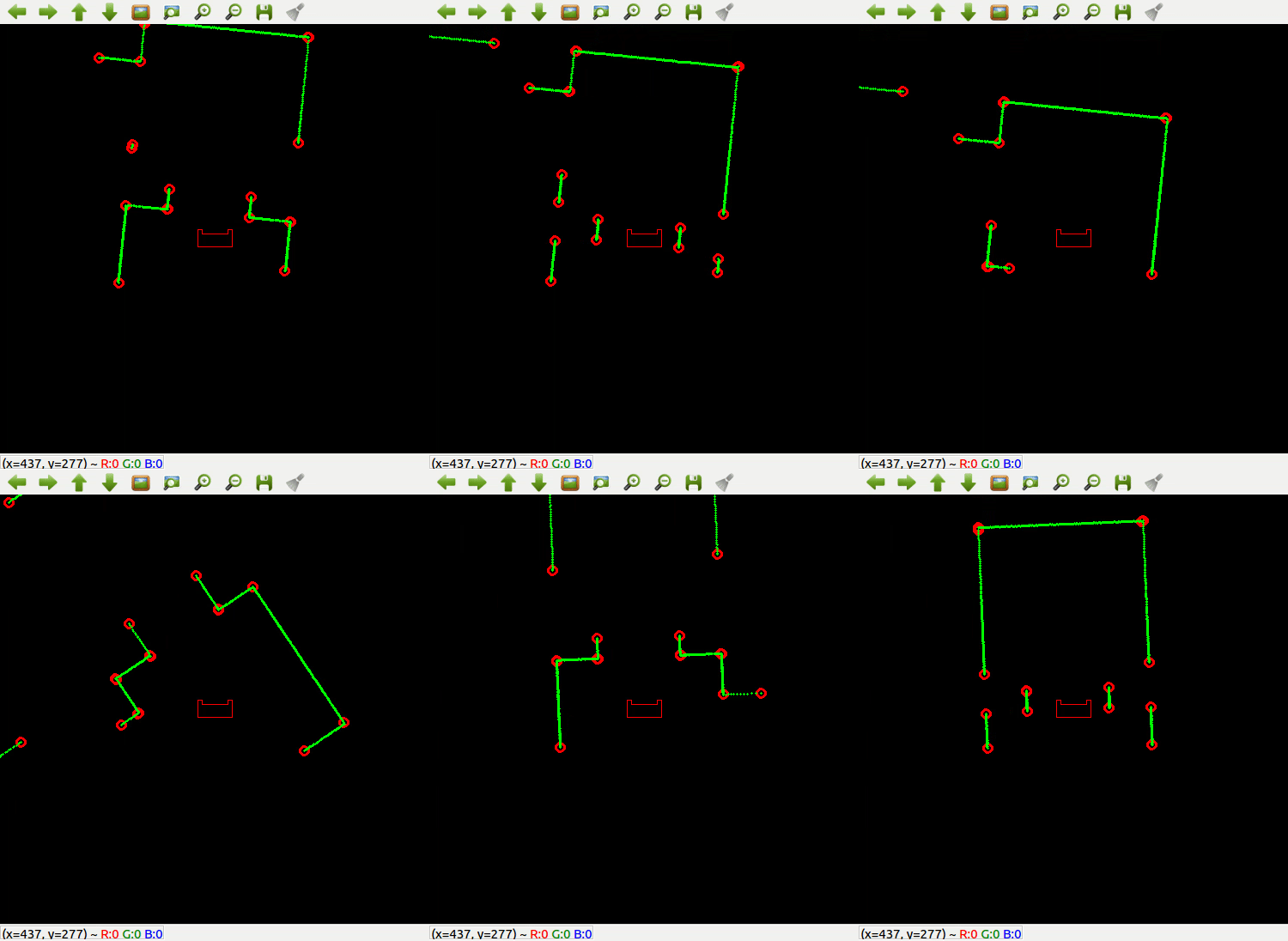
The Feature Recognition algorithm reads PICO’s laser rangefinder data and recognizes three types of features:
- A corner that is seen in its entirety
- A corner that is seen from one side and inferred
- The end of a wall’s observation caused by occlusion of PICO’s blind spot.
Segmentation
The Feature Recognition algorithm is based on detecting segments of walls. It constructs a line segment and sees if it is a good fit for the data, if not it splits and adapts the segments until everything fits. The end points of the segments are saved as features.
Line Fitting
The segmentation algorithm only finds the first and last point making up a wall, the measurements for these contain noise. To mitigate that noise a line is fitted through all the points making up the wall segment. This is done using a Total Least Squares regression. This looks at deviations in two directions and fits a line that minimizes the orthogonal distance between the points and the line.
Corner Detection
Due to the nature of the segmentation algorithm the segments on opposite sides of a corner do not touch but they are spaced one laserdata point apart. To detect a completely visible corner the list of features is iterated over. If two consecutive features are very close together they make up a corner of type 1. The intersection point of the two regression lines on either side of the corner is then set as the corner’s location.
If there is a jump in the distance between two consecutive features but the angle between them, as seen from PICO, is small the closest of these two features is an inferred corner of type 2. The intersection between the regression line for the visible segment and a line drawn from PICO to the last element of the segment is set as the location of the corner. The other feature is an occluded wall end of type 3.
The first and last features detected sit at the edges of PICO’s field of view, these are always occluded wall ends of type 3. Features of type 3 are not used in the SLAM algorithm.
Corner Identification
In the hospital map that is provided the all corners are labeled. The position and orientation of PICO is provided by SLAM. Using PICO’s localization the coordinates of the map’s coordinates are transformed to PICO’s reference. Then for every detected corner the distance to the map’s corners is computed. If it is smaller than a certain threshold the detected corner gets the label of the map’s corner. If a detected corner can not be matched it gets the label -1. This could occur if there is an object observed that is not in the provided map, like a moving person, or if the localization estimate is incorrect.
SLAM
The chosen algorithm for localizing PICO and updating the map with real-world information is fastSLAM2, with the actual implementation largely supported by online lectures and research by Cyrill Stachniss.
The core idea of fastSLAM (especially in its comparison to normal Extended Kalman Filter (EKF) Particle Filter SLAM approaches) is the concept that the relationship between a robot's motion and sensors, and the outside world, is such that given a perfect model, landmarks will always be in the same position. In a more reduced form, using a particle filter to sample the robot's path, this relationship still holds, allowing one to model the outside world as a list of landmarks with a much more static nature than an ever growing hypothetical map of the outside world (which is what normal EKF filters do). Due to this, the measurement covariance element of a single landmark is nothing more than a 2x2 matrix, which, given that it has to be inverted and the most efficient inversion algorithm is O(n3), is a very big deal.
The core idea of fastSLAM2 is to patch a hole in fastSLAM1 where information is lost. Specifically, in the part of the algorithm that is described as 'sampling the pose' - making a prediction, for a particle, of the robot state in the next measurement iteration - fastSLAM2 does not make use of that iteration's measurements. However, by nature of the above relationship, measurements and odometry data are almost equivalently tied to the robot's behaviour. As such, fastSLAM2 includes measurement data when it predicts a robot's state, which, as the paper linked above explains, dramatically improves performance of the algorithm.
Map Updating
This section covers the system functionalities responsible for (intelligent) navigation. All functions here have read access to the world model’s internal map and LRF envelope. The navigation can be split into two parts: pathfinding and path movement.
Path Finding
For pathfinding, A* is chosen. A* is a pathfinding algorithm based and built on Dijkstra's Algorithm. Dijkstra's Algorithm looks at every available cell all around the start point, until it reaches the goal. A* is smarter, and attaches more value to the cells towards the goal. Because of this, A* needs fewer iterations and is faster.
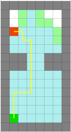
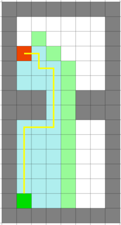
Figure 1: Difference between Dijkstra's algorithm (left figure) and A* (right figure).
Path Movement
Path movement translates the points of the trajectory of the A* algorithm to a vector of necessary x and y speed values for the PICO robot to follow the trajectory.
List of Meetings
| Date/Time | Roles | |
|---|---|---|
| Meeting 1 | 01-05-2020
11:00 |
Chairman: Bas
|
| Meeting 2 | 04-05-2020
11:00 |
- |
| Meeting 3 | 08-05-2020
11:00 |
Chairman: Max
|
| Meeting 4 | 11-05-2020
10:00 |
- |
| Meeting 5 | 12-05-2020
10:00 |
- |
| Meeting 6 | 15-05-2020
11:00 |
Chairman: Dominic
|
| Meeting 7 | 18-05-2020
11:00 |
- |
| Meeting 8 | 22-05-2020
11:00 |
Chairman: Roel
|
| Meeting 9 | 27-05-2020
15:00 |
- |
| Meeting 10 | 29-05-2020
11:00 |
Chairman: Rob
|
| Meeting 11 | 02-06-2020
11:00 |
- |
| Meeting 12 | 04-06-2020
11:00 |
Chairman: Ananth
|
Links
These will probably be invite-based but a backup link could be useful.
Gitlab: https://gitlab.tue.nl/MRC2020/group4
Overleaf design document: https://www.overleaf.com/project/5eabeda72b3e4100010f8b40
