Firefly Eindhoven - Localization - Top Camera: Difference between revisions
| Line 7: | Line 7: | ||
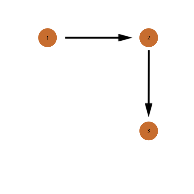
[[File: TopCamVector1.png ||thumb|right|200px|Vectors between the LEDs. LEDs 1 and 2 are the top LEDs]] | [[File: TopCamVector1.png ||thumb|right|200px|Vectors between the LEDs. LEDs 1 and 2 are the top LEDs]] | ||
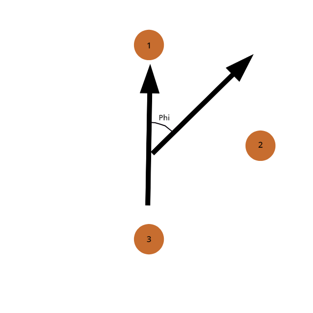
[[File: TopCamVector2.png ||thumb|right|200px|Vectors pointing in the phi is zero direction and the direction of the drone. LEDs 1 and 2 are the top LEDs]] | [[File: TopCamVector2.png ||thumb|right|200px|Vectors pointing in the phi is zero direction and the direction of the drone. LEDs 1 and 2 are the top LEDs]] | ||
To get from the I shape to the L shape, the geometry of the code had to be changed. It was decided to create vectors between the three points, and to | To get from the I shape to the L shape, the geometry of the code had to be changed. It was decided to create vectors between the three points, and to find the direction between the two vectors. This was done by rotating the first vector 90 degrees clockwise and taking the dot product between the rotated vector and the second vector. | ||
This uniquely determines which of the two vectors is part of the front of the drone, because if the angle is negative (meaning turned less than 180 degrees counter clockwise with respect to the previous vector), this means that the second vector could be made by rotating the first one counter clockwise, meaning that the second vector is the vector between the two LEDs at the front of the drone. If the angle is positive, the second vector could be made by rotating the first one clockwise, and therefore the first vector is the vector between the two LEDs at the front of the drone. | |||
Bearing this in mind, the angle of the drone can be determined by creating a vector perpendicular to the vector between the points in the front and exactly in the middle of those two points. The angle of the drone will be the angle between an arbitrary vector that is pointing into the phi is zero direction and the vector just explained. The x and y position of the drone can be easily calculated by taking the average between the two outer points. | |||
===Getting from one to multiple drones=== | ===Getting from one to multiple drones=== | ||
Revision as of 12:58, 24 May 2018
Software procedure
- Description of C++ procedure
- Links to the code (preferably through Github)
Extension to multidrone procedure
From I to L shape
To get from the I shape to the L shape, the geometry of the code had to be changed. It was decided to create vectors between the three points, and to find the direction between the two vectors. This was done by rotating the first vector 90 degrees clockwise and taking the dot product between the rotated vector and the second vector.
This uniquely determines which of the two vectors is part of the front of the drone, because if the angle is negative (meaning turned less than 180 degrees counter clockwise with respect to the previous vector), this means that the second vector could be made by rotating the first one counter clockwise, meaning that the second vector is the vector between the two LEDs at the front of the drone. If the angle is positive, the second vector could be made by rotating the first one clockwise, and therefore the first vector is the vector between the two LEDs at the front of the drone.
Bearing this in mind, the angle of the drone can be determined by creating a vector perpendicular to the vector between the points in the front and exactly in the middle of those two points. The angle of the drone will be the angle between an arbitrary vector that is pointing into the phi is zero direction and the vector just explained. The x and y position of the drone can be easily calculated by taking the average between the two outer points.
Getting from one to multiple drones
To get the camera to detect multiple drones, a distinction had to be made between LEDs of one drone and another. To do this, a K-means algorithm was used to find ceil([math]\displaystyle{ \frac{nr_{leds}}{3} }[/math]) clusters. These clusters of LEDs were analyzed to see if the clusters had more or less than three points, or if these points were too close together or too far away to be a drone. If any of these conditions were true, the cluster is deleted from the list. If no clusters are left after this procedure, the exposure of the camera would be changed to find more or less LEDs. The clusters of three LEDs would then be given an ID based on the previous positions of the drones, if available. If the program finds an extra drone or it is the first frame, the IDs are given in the order the K-means gives the results, which can be seen as random.
Design decisions
During the design, certain decisions had to be made in terms of robustness and accuracy. These decisions are summarized below. The first design decision that had to be made was which points to use to calculate the angle. Using two points will be less accurate than using three points, but taking the third point into account will decrease the robustness as checking if this point is on the right line to validate the results afterwards will not make sense if this point is also used in the calculations. It was decided to go with the two points and using the third point as a check because if the point was too far off to be of use, the check after the K-means would already have gotten rid of the drone and the robustness was valuated as more important than the accuracy due to this. The second design decision that had to be made was when to throw away results and when to keep them after the K-means. This is because a four LED result could still be a drone but a fourth LED could have appeared due to reflections. Checking these results would make sure that more drone results will be displayed and the frequency that a drone would not be detected for a single frame would decrease, but the computation time would take longer and if the algorithm would be wrong and would detect a drone without there being one, the drone which it detected wrongly would think it would be at a completely different position and therefore would suddenly give a high thrust in an unexpected direction, potentially ruining the show. Therefore the robustness of the program would decrease greatly if not implemented correctly. For this reason, it was decided not to implement this.

