Embedded Motion Control 2017 Group 1
Group Members
| Name: | Student id: |
| Karel van de Plassche | 0653197 |
| Joey Hendriks | 0773023 |
| Ioannis-Dionysios Bratis | 0978560 |
| Jad Haj Mustafa | 0979428 |
| Jip Reinders | 0853301 |
| Juliana Langen | 0988532 |
| Yanick Douven | Tutor |
Initial Design
Link to the PDF version of the initial design: PDF
Overview
In this article a summary of the embedded software design is presented.This software is used to solve the following problems:
- Corridor challenge: The robot should autonomously drive through a corridor and take the first exit.
- Maze challenge: The robot should autonomously drive through a maze and find the exit.
Requirements/Specifications
| Type | Requirement | Specification |
|---|---|---|
| General | - Be able to 'solve' any given configuration of walls.
- Do not bump into walls: Detect walls, define minimum distance. - Move autonomously: Detect openings, junctions, crossings, dead ends, open spaces etc. and make optimal decision. - Software easy to set up: As defined on general wiki page. - Only one executable is allowed. The software will be updated on the robot before the challenge starts. - Do not stand still too long: Detect time that robot is standing still, initiate movement after set time. - Stop movement after task is achieved. |
- The maximal translational velocity of PICO is 0.5 m/s.
- The maximal rotation velocity of PICO is 1.2 rad/s. - Pico should not stay still for more than 30 seconds. - Complete task within 2 attempts. - The LRF has a width of about 4 rad (from -2 to 2 rad), with a resolution of about 1000 points. |
| Corridor | - Finish the corridor challenge fast: Detect opening either on left/right, take turn, stop after finish line. | - Back wheel across finish line within 5 minutes. Terminate afterwards. |
| Maze | - Finish the maze challenge fast: Navigate maze, find exit, stop after finish line.
- Be able to reconstruct maze. - Determine difference between dead end and door. - Deal with open spaces. - Deal with loops. - Be able to open doors. |
- Back wheel across finish line within 7 minutes. Terminate afterwards.
- Decide where to go when at a T-junction or crossing. - Ring a bell and wait at a dead end to check for a door. |
Functions
| Function | Description | |
|---|---|---|
| Low-level | initialize | Initialize actuators |
| readSensors | Read the odometer and laser data | |
| turnLeft | Turn 90° left | |
| turnRight | Turn 90° right | |
| turnAround | Turn 180° | |
| stopMovement | Stop omniwheels | |
| driveForward | Accelerate or decelerate | |
| driveBackward | Drive backward | |
| driveLeft | Move left | |
| driveRight | Move right | |
| ringBell | Ring the bell of the door. | |
| Mid-level | detectWall | Detect a wall (~30cm) |
| detectCorner | Detect a corner (crossing of two walls) | |
| detectDeadEnd | Detect a dead end | |
| detectFinish | Detect the finish line | |
| detectOpenSpace | Detect an open space | |
| detectOpenWorld | Detect if in the open world (like the maxe exit) | |
| detectTJunction | Detect a T-junction (where three corridors meet) | |
| detectCrossing | Detect a crossing (where the four corridors meet) | |
| shutDown | Terminate robot, if required | |
| checkDoor | Send a signal and wait x seconds | |
| chooseCorridor | Choose which corridor to take | |
| High-level | stayBetweenWalls | Stay in the center of two walls |
| createMap | Build map of surroundings | |
| trackPath | track the path through the map | |
| detectLoop | Detect a loop in the maze | |
| detectStack | Detect if stuck | |
| optimalDecision | Decide next move based on given algorithm |
Components
The PICO robot consists of multiple components which are listed below:
- Sensors:
- Laser Range Finder (LRF): Through the LRF on the PICO one can detect the distance to an object.This is accomplished by sending a laser pulse in a narrow beam towards the object and measuring the time taken by the pulse to be reflected on the target and returned to the sender.
- Wheel encoders (odometry): Through the encoder one can obtain the speed of the wheels which can be used to control PICO based on the provided data.
- Actuators:
- Holonomic base (omni-wheels)
- Pan-tilt unit for head
- Computer
- Ubuntu14.04
- Intel I7
Interfaces

Update - Week of May 14th, 2017
Progress
Initial programming for the corridor challenge was completed and tested. The functions created this week include gap detection, potential field implementation (for actuation control of Pico) and a main function to initiate the required actions. After testing the code using the simulator and Pico itself the next developments for the code are as follows: add a function that determines the location of walls and gaps, add a state manager that will keep track of the position of Pico relative to the walls and gaps and make decisions, and refine the potential field function so Pico moves straighter in the corridor.
Testing
The current design was tested using the simulator and Pico robot with varying degrees of success. Currently Pico can find the corridor and initiate the turn but does not make a wide enough turn to avoid the corners. Pico moves from side to side while driving through a corridor as well.
Presentation
The initial design was presented on May 17th, 2017. Link to a PDF copy of the presentation slides: File:Presentation EMC intermediate group 1 - final.pdf
Corridor Challenge 2017
Corridor Competition
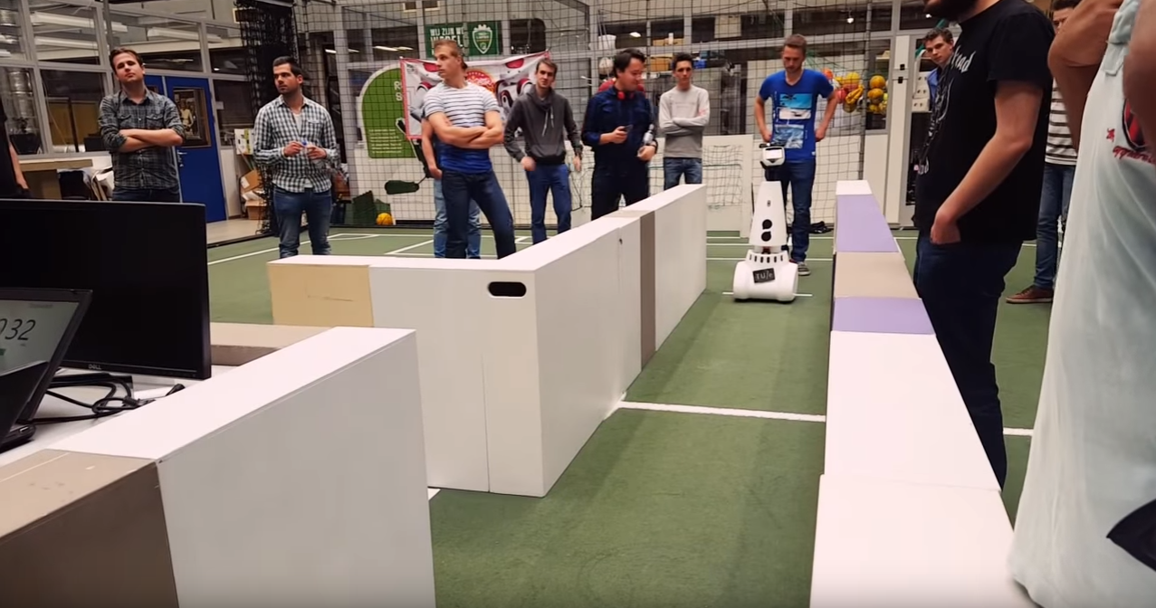
During this competition we were supposed to have the robot autonomously drive through a corridor, identify an exit and take that exit in order to complete the challenge. The precise location of the exit as well as whether the exit is to the left or the right of the corridor are not known in advance. Pico uses the laser data for the implementation of the potential fields method in order to keep him in the middle of the corridor.Furthermore we used a sensing function to indicate whether there are walls or a gap in the corridor.Finally a state supervisor when should turn right or left according to where the exit(gap) has been placed
Potential Fields
After going through multiple path planning methods and algorithms we finally decided to choose the potential fields method.The basic concept of this method is the following:For every laser point available(1-1000 beams) a corresponding virtual repulsive force is applied to the PICO,that forces the robot to move away from obstacles or walls.Moreover,a virtual attractive force is applied to the robot in order to force it to move towards the setpoint,namely the desired direction.As soon as PICO gets really close to either a wall or an obstacle the repulsive forces grow bigger, whereas they become smaller when it is navigating in α safe distance from them.The exact opposite is occurring for the attractive force.Finally,The summation of the attractive force and all the repulsive forces will keep the robot in the middle of the corridor and navigating towards the given setpoint. As explained before, the potential fields method is used as collision avoidance as well,since with this method PICO will never drive into a wall.

Sensing
State Supervisor
Corridor Challenge Evaluation
The corridor challenge occurred on May 24th,2017 and our design achieved excellent results.We managed to get the first place of the competition with a time of 14.66 seconds on our first implementation,which at that point of time had only been tested on simulation. During our second attempt,which was tested on the actual robot we managed to complete the corridor challenge successfully with a time of 18 seconds.In order to succeed finishing the corridor competition multiple corridors were created for testing.These included different widths,for both the corridor and the exit,cracks in the walls as well as walls not correctly aligned.Out of the ideas implemented we can use the potentials fields method also for the maze challenge.The sensing function needs to be adjusted in order to detect all kinds of junctions and open spaces and the supervisor needs to be upgraded in order to to finish the maze successfully. 1st attempt:
 |
2nd attempt:
|
Maze Challenge 2017
Final Presentation
Our final design was presented on June 7th, 2017. Link to a PDF copy of the presentation slides: File:Presentation EMC final group 1 - final.pdf