Embedded Motion Control 2017 Group 1: Difference between revisions
| Line 310: | Line 310: | ||
[[File:corridor simulation midpoint tracking.gif|400px|center|frame|corridor simulation with an exit on the left side of the corridor,midpoint tracking included.]] | [[File:corridor simulation midpoint tracking.gif|400px|center|frame|corridor simulation with an exit on the left side of the corridor,midpoint tracking included.]] | ||
After multiple testing, we realized a possible bug by using this implementation.If there is a jump in the midpoint's distance, leading to a midpoint which is located in an unaccessible location for the robot, this implementation might force PICO to run into a wall in order to access that midpoint.However, the repulsive forces of the potential fields will prevent the robot from crushing into the walls.Nevertheless,PICO will keep tracking that midpoint and hence leading to an undesired movement. | |||
===Open Spaces=== | ===Open Spaces=== | ||
Revision as of 17:41, 18 June 2017
Group Members
| Name: | Student id: |
| Karel van de Plassche | 0653197 |
| Joey Hendriks | 0773023 |
| Ioannis-Dionysios Bratis | 0978560 |
| Jad Haj Mustafa | 0979428 |
| Jip Reinders | 0853301 |
| Juliana Langen | 0988532 |
| Yanick Douven | Tutor |
Initial Design
Link to the PDF version of the initial design: PDF
Overview
In this article a summary of the embedded software design is presented.This software is used to solve the following problems:
- Corridor challenge: The robot should autonomously drive through a corridor and take the first exit.
- Maze challenge: The robot should autonomously drive through a maze and find the exit.
Requirements/Specifications
| Type | Requirement | Specification |
|---|---|---|
| General | - Be able to 'solve' any given configuration of walls.
- Do not bump into walls: Detect walls, define minimum distance. - Move autonomously: Detect openings, junctions, crossings, dead ends, open spaces etc. and make optimal decision. - Software easy to set up: As defined on general wiki page. - Only one executable is allowed. The software will be updated on the robot before the challenge starts. - Do not stand still too long: Detect time that robot is standing still, initiate movement after set time. - Stop movement after task is achieved. |
- The maximal translational velocity of PICO is 0.5 m/s.
- The maximal rotation velocity of PICO is 1.2 rad/s. - Pico should not stay still for more than 30 seconds. - Complete task within 2 attempts. - The LRF has a width of about 4 rad (from -2 to 2 rad), with a resolution of about 1000 points. |
| Corridor | - Finish the corridor challenge fast: Detect opening either on left/right, take turn, stop after finish line. | - Back wheel across finish line within 5 minutes. Terminate afterwards. |
| Maze | - Finish the maze challenge fast: Navigate maze, find exit, stop after finish line.
- Be able to reconstruct maze. - Determine difference between dead end and door. - Deal with open spaces. - Deal with loops. - Be able to open doors. |
- Back wheel across finish line within 7 minutes. Terminate afterwards.
- Decide where to go when at a T-junction or crossing. - Ring a bell and wait at a dead end to check for a door. |
Functions
| Function | Description | |
|---|---|---|
| Low-level | initialize | Initialize actuators |
| readSensors | Read the odometer and laser data | |
| turnLeft | Turn 90° left | |
| turnRight | Turn 90° right | |
| turnAround | Turn 180° | |
| stopMovement | Stop omniwheels | |
| driveForward | Accelerate or decelerate | |
| driveBackward | Drive backward | |
| driveLeft | Move left | |
| driveRight | Move right | |
| ringBell | Ring the bell of the door. | |
| Mid-level | detectWall | Detect a wall (~30cm) |
| detectCorner | Detect a corner (crossing of two walls) | |
| detectDeadEnd | Detect a dead end | |
| detectFinish | Detect the finish line | |
| detectOpenSpace | Detect an open space | |
| detectOpenWorld | Detect if in the open world (like the maxe exit) | |
| detectTJunction | Detect a T-junction (where three corridors meet) | |
| detectCrossing | Detect a crossing (where the four corridors meet) | |
| shutDown | Terminate robot, if required | |
| checkDoor | Send a signal and wait x seconds | |
| chooseCorridor | Choose which corridor to take | |
| High-level | stayBetweenWalls | Stay in the center of two walls |
| createMap | Build map of surroundings | |
| trackPath | track the path through the map | |
| detectLoop | Detect a loop in the maze | |
| detectStack | Detect if stuck | |
| optimalDecision | Decide next move based on given algorithm |
Components
The PICO robot consists of multiple components which are listed below:
- Sensors:
- Laser Range Finder (LRF): Through the LRF on the PICO one can detect the distance to an object.This is accomplished by sending a laser pulse in a narrow beam towards the object and measuring the time taken by the pulse to be reflected on the target and returned to the sender.
- Wheel encoders (odometry): Through the encoder one can obtain the speed of the wheels which can be used to control PICO based on the provided data.
- Actuators:
- Holonomic base (omni-wheels)
- Pan-tilt unit for head
- Computer
- Ubuntu14.04
- Intel I7
Interfaces

Update - Week of May 14th, 2017
Progress
Initial programming for the corridor challenge was completed and tested. The functions created this week include gap detection, potential field implementation (for actuation control of Pico) and a main function to initiate the required actions. After testing the code using the simulator and Pico itself the next developments for the code are as follows: add a function that determines the location of walls and gaps, add a state manager that will keep track of the position of Pico relative to the walls and gaps and make decisions, and refine the potential field function so Pico moves straighter in the corridor.
Testing
The current design was tested using the simulator and Pico robot with varying degrees of success. Currently Pico can find the corridor and initiate the turn but does not make a wide enough turn to avoid the corners. Pico moves from side to side while driving through a corridor as well.
Presentation
The initial design was presented on May 17th, 2017. Link to a PDF copy of the presentation slides: File:Presentation EMC intermediate group 1 - final.pdf
Corridor Challenge 2017
Corridor Competition
During this competition we were supposed to have the robot autonomously drive through a corridor, identify an exit and take that exit in order to complete the challenge. The precise location of the exit as well as whether the exit is to the left or the right of the corridor are not known in advance. Pico uses the laser data for the implementation of the potential fields method in order to keep him in the middle of the corridor.Furthermore we used a sensing function to indicate whether there are walls or a gap in the corridor.Finally a state supervisor when should turn right or left according to where the exit(gap) has been placed
Potential Fields
After going through multiple path planning methods and algorithms we finally decided to choose the potential fields method.The basic concept of this method is the following:For every laser point available(1-1000 beams) a corresponding virtual repulsive force is applied to the PICO,that forces the robot to move away from obstacles or walls.Moreover,a virtual attractive force is applied to the robot in order to force it to move towards the setpoint,namely the desired direction.As soon as PICO gets really close to either a wall or an obstacle the repulsive forces grow bigger, whereas they become smaller when it is navigating in a safe distance from them.The exact opposite is occurring for the attractive force.Finally,The summation of the attractive force and all the repulsive forces will keep the robot in the middle of the corridor and navigating towards the given setpoint. As explained before, the potential fields method is used as collision avoidance as well,since with this method PICO will never drive into a wall.

Different weight constants were used for both the attractive and the repulsive forces as well as for the rotational and translational velocities.The total amount of forces for both the x and y direction are computed separately,and then transformed into velocities for which weighting constants are used again.By using the potential fields method the angle computed in comparison to the 500th beam always tries to get a zero value and is used to compute the rotational velocity.Hence PICO will always turn in the desired direction and the bigger the angle,the faster will PICO complete the turn.The formulas for "translational","rotational" velocities are:
[math]\displaystyle{ v_x = w_{vx} * Ftot_{x} }[/math]
[math]\displaystyle{ v_y = w_{vy} * Ftot_{y} }[/math]
[math]\displaystyle{ w = w_{w} * \phi }[/math]
Finally in order to ensure that our code will work on simulations and on the actual robot all velocities are saturated within certain values,namely 0.5 m/s for the translational speed and 1.2 rad/s for the rotational speed.
The first thing we needed to test with this method was whether the collision avoidance skill works on the actual robot.After setting no setpoint,the repelling force seems to work sufficiently enough:
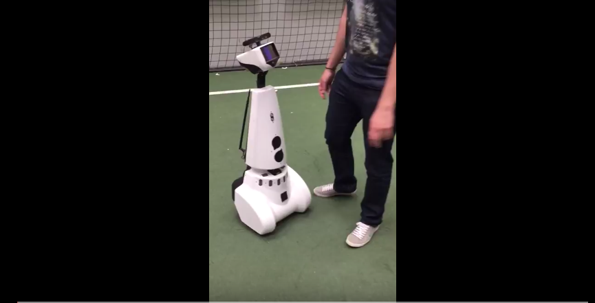 |

By applying the potential fields method it is possible to solve a very simple maze with one possible direction to go. That is achieved by applying a small setpoint of 0.1("carrot on a stick method"),while at the same time PICO is guaranteed to never collide with the wall because of the repulsive force. A demonstration is presented below:
 |
Sensing
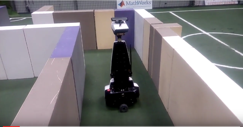
For the detection of the corridors, a limited range method for the laser data was used.Through this method possible corridors can be detected,which can be seen in the following figures.
The first step is to define the max range and check for all the beams which of them correspond to a lower distance then the max range.Then the maximum detection range is decreased until the percentage condition is met(60% of all beams).After that, all distances bigger than this maxrange distance are adjusted to this maxrange,including the very high distances.Finally an array is created that returns the number of gaps or walls,and in case of a gap it returns the x and y coordinates of the midpoint of that gap.


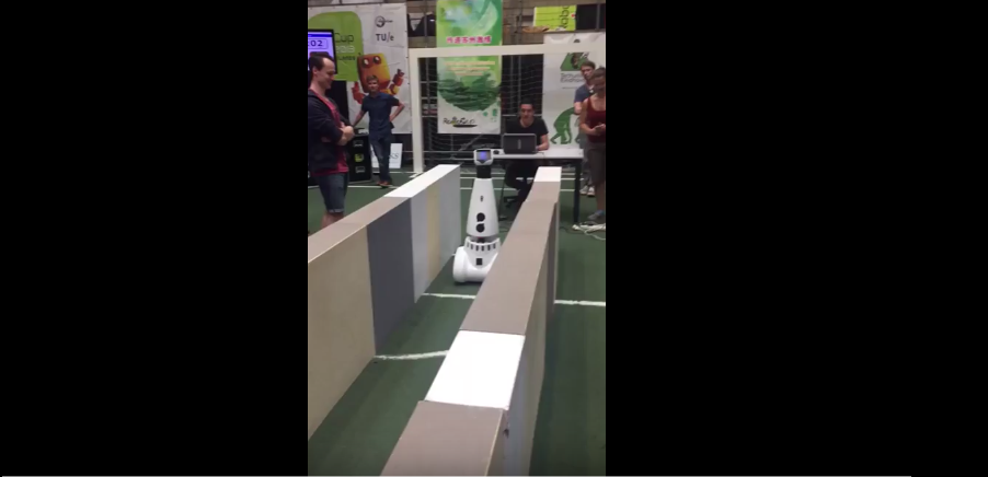
State Supervisor
In this function the supervisor checks the number of gaps provided by the sensing function.In case there a gap, the supervisor then checks the beams on the right and left side and according to the detected gap it decides to turn either left or right.A simulation of a corridor with a right exit is provided below.

Corridor Challenge Evaluation
The corridor challenge occurred on May 24th,2017 and our design achieved excellent results.We managed to get the first place of the competition with a time of 14.66 seconds on our first implementation,which at that point of time had only been tested on simulation. During our second attempt,which was tested on the actual robot ,but without using a decision algorithm, we managed to complete the corridor challenge successfully within a time of 18 seconds.In order to succeed finishing the corridor competition multiple corridors were created for testing.These included different widths,for both the corridor and the exit,cracks in the walls as well as walls not correctly aligned.Out of the ideas implemented we can use the potentials fields method also for the maze challenge.The sensing function needs to be adjusted in order to detect all kinds of junctions and open spaces and the supervisor needs to be upgraded in order to to solve the maze successfully.
1st attempt:
 |
2nd attempt:
|
Maze Challenge 2017
Software Architecture
Supervisor
Potential Fields
Visualization
Detection Circle
Midpoint Tracking
One of the first ideas implemented by our group is since we compute through the sensing function always the x and y coordinates of the midpoint we can hence track it and base our movement on that.The setpoint for the potential fields is now the midpoint given.Such a simulation is provided below:
After multiple testing, we realized a possible bug by using this implementation.If there is a jump in the midpoint's distance, leading to a midpoint which is located in an unaccessible location for the robot, this implementation might force PICO to run into a wall in order to access that midpoint.However, the repulsive forces of the potential fields will prevent the robot from crushing into the walls.Nevertheless,PICO will keep tracking that midpoint and hence leading to an undesired movement.
Open Spaces
Dead End and Door Detection
Pledge Algorithm

To prevent Pico being stuck in loops, the pledge algorithm was used as the decision making strategy. Pledge counts the amount of left or right turns the robot took. Based on this count, the algorithm decides whether to turn left, right or continue straight. Pledge works as followed:
- Initially the counter is 0, thus the initial direction that Pico is facing is remembered.
- Whenever the counter is 0, Pico moves straight unless this isn’t possible anymore, for example due to a right turn.
- Every time Pico turns 90 degrees right, the counter is increased by 1.
- Every time Pico turns 90 degrees left, the counter is decreased by 1.
- When for example the counter was increased from 0 to 1 due to a right turn, Pico follows the outer wall until the counter is 0 again. Apart from special U-turn cases depicted in the figure, this means that when the counter is -1 or smaller, Pico prefers to turn right whenever possible.
- When the counter is 1 or larger, Pico prefers to turn left whenever possible.
- At a dead end, Pico turns 180 degrees right or left depending on the counter. The counter is increased/decreased by 2.

The advantage of the pledge algorithm was that it doesn’t require any mapping, it was only required that Pico recognizes the junctions and the turns. Pledge however doesn’t work when the robot starts outside the maze and has to find its way in: the algorithm is only valid when starting inside the maze and the exit is on the outside. According to the rules of this project, it was guaranteed that Pico always start in the inside and had to move out, thus pledge was a safe choice as the maze solving strategy.
Random Walk Algorithm
In the case that Pico doesn’t recognize a junction completely and drives through it using just the potential field, the counter of the pledge algorithm will no longer be valid. In some mazes this could mean that due to a wrong counter, the robot will be stuck in a loop. If this happens during the first attempt, the random-walk algorithm will be used during the second attempt instead of pledge.
As the name suggests, the random-walk algorithm randomly chooses one of the available directions at a junction. Every time the random-walk algorithm is used, the seed of the random-function is changed to keep it actually random. Though since it is random and Pico doesn’t make any “smart” decisions, it isn’t the most robust method in terms of how long it will take till Pico reaches the exit. However. the main idea is that Pico will eventually reach the exit despite the time. This is a very simple algorithm and doesn’t require a counter. The random-walk algorithm is thus mainly used as a back-up plan.
Final Presentation,Improvements
Our final design was presented on June 7th, 2017. Link to a PDF copy of the presentation slides: File:Presentation EMC final group 1 - final.pdf
Based on this presentation we discovered some flaws in our design and decided to re-think our whole strategy while keep some working parts of the code. The robot moves inside a corridor and is in the state LOOKING_FOR_SIDE by using the node recognizing function we used before.This function as mentioned before,recognizes all available junctions namely:
STRAIGHT,CROSS,T_JUNCTION_RF,T_JUNCTION_FL,T_JUNCTION_RL,CORNER_LEFT,CORNER_RIGHT,DEAD_END,OPEN_SPACE_LEFT,OPEN_SPACE_RIGHT,OPEN_SPACE_MIDDLE
Then as soon as PICO recognizes a junction it calls the pledge algorithm in order to determine which direction it will follow. Based on this information,the desired midpoint is stored for future use. The next step includes PICO going to MOVE TO MIDPOINT state.In this state,the midpoint is updated to the closest midpoint available(by comparing the distance formed by the initial midpoint and the new ones). After that, the x coordinate of the updated midpoint is checked in order to establish whether the robot has reached the middle of the junction.Then, according to which midpoint you have(left or right) you enter the state ROTATE_LEFT or ROTATE_RIGHT.PICO will continue to turn until it reaches the point where the y-coordinate of its current position is the same as the stored midpoint.Finally the robot will move forward towards the corridor until it detects walls on both left and right side, guaranteeing thus, that a complete turn is accomplished.
File:Final Idea design EMC group 1 sketch.pdf