Embedded Motion Control 2016 Group 3: Difference between revisions
| Line 211: | Line 211: | ||
=Decision Making - Random Walk= | =Decision Making - Random Walk= | ||
The simplest approach of making decisions in the maze is to make random decisions, which is our first implementation in the software, as it\’s the easiest one and it is supposed to be our back-up plan, if our decision-making algorithm fails. According to the "random walk", when PICO faces more than one option to go, it randomly picks one and sticks to it, with the use of the "transition conditions" that were mentioned above. Priority is given in the dead ends and the open space, which are special cases and when detected, PICO must act accordingly and stop everything else it\’s currently doing. | |||
The function random_walk() checks all the available options (straight/left/right/dead end/open space) and generally picks randomly one of them, when the "transition conditions" allow it of course. The random choice is being done with the function rand(). There is one precaution which is taken into account and that is that when PICO is in an open space and it follows the closest wall, the next decision it must take in the next junction must be the same as the wall it\’s following e.g. if it\’s following the left wall the next decision must be left. In this way, PICO will make sure that it will get out of the open space which is a very difficult case and will not roam in the open space aimlessly. So if the opposite turn is selected then the function is called again, until an acceptable decision is selected. | |||
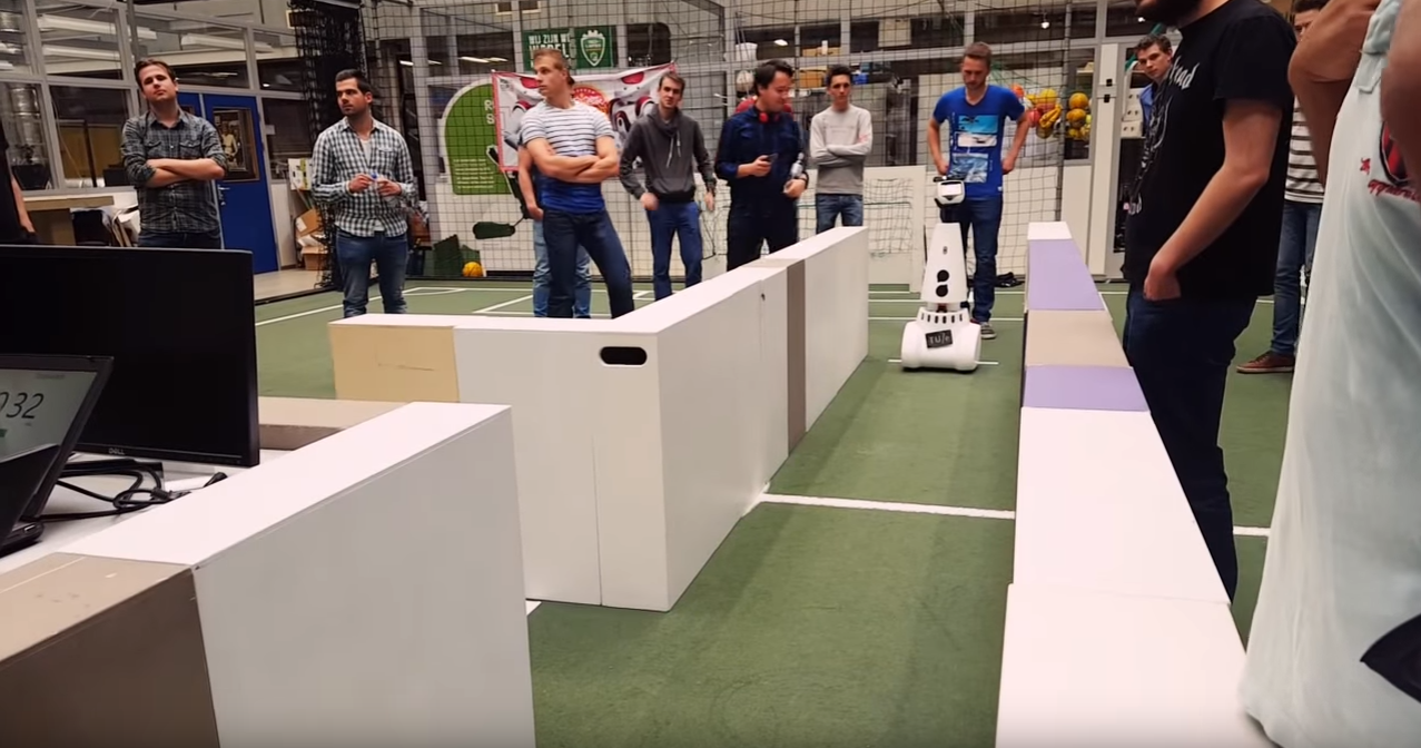
Below, the solving of the maze that was used in the maze challenge with the random_walk technique is depicted. | |||
('''Simulation''' of maze with random_walk) | |||
=Decision Making - Pledge Algorithm= | =Decision Making - Pledge Algorithm= | ||
=Maze Challenge Evaluation= | =Maze Challenge Evaluation= | ||
Revision as of 10:30, 16 June 2016
Group Members
| 0976155 | Aditya Kamath | a.kamath@student.tue.nl |
| 0980790 | Alexis Siagkris-Lekkos | a.siagkris-lekkos@student.tue.nl |
| 0976940 | Amrith Vel Arul Kumar | a.v.arul.kumar@student.tue.nl |
| 0976467 | Ayush Kumar | a.kumar.1@student.tue.nl |
| 0978245 | Mahmoud Al Abbassi | m.alabbassi@student.tue.nl |
Initial Design Idea
Here the first approach to the problem is presented, namely Design Document 1 that describes the initial design idea for a robot that navigates through a maze and finds the exit autonomously.
Overview
This article presents a summary of the software design to solve the following challenges with the Pico robot.
- Corridor competition: To follow a corridor and take the first exit.
- Maze competition: To solve and exit an unknown maze.
The project is divided in the following aspects:
- Requirements
- Specifications
- Functions
- Components
- Interfaces
Requirements/Specifications
For the brainstorming phase, the requirements and specifications are described in one section as the specifications cannot be determined without an introduction to the robot hardware. The requirements of the robot are as follows:
- The robot should not stand still for more than 30 seconds
- The robot should not collide with the walls
- The robot should solve the undisclosed maze and exit within 5 minutes
- The software should store the maze as a map and the robot should be able to revert back to the last known state/position in case of any error.
- The robot should be able to distinguish between the door and dead ends and send out a request to open the determined door
- The robot should determine if the maze is solved and should stop accordingly
- The optimal exit angle should be calculated (how much wheel actuation is necessary for the turn)
Functions
Functions are divided into low, mid and high level. High level functions are not required for corridor challenge.
Low level
| initialization: | Initialization of sensors, actuators |
| read_inputs: | Read laser (LRF) and encoders (walls as reference) |
| drive_forward: | accelerate, decelerate can be separate sub-functions |
| drive_sideways: | Motor control for sideways motion |
| left_turn: | Turn 90o left( doesn’t necessarily need to be at standstill) |
| right_turn: | Turn 90o right |
| U_turn: | Turn 180o left |
| standstill: | Stay at the same position with zero speed, for instance when it waits for the door to open |
Middle level
| get_distance: | Measure the distance to an obstacle (wall, door, anything) |
| avoid_collision: | Keep a safety distance from walls (possible sub-functions: slow down when you\’re close, completely stop when you\’re ready to crash) |
| kill_switch: | Polling for the manual switch to shut the robot, when needed by us |
| finishing_line: | A function to identify the finishing line and shut down the robot (possible options: use kill-switch or detection of being far away from any wall i.e. no walls in front or to the right/left) |
| find_gaps: | Identify all possible passages, corridors (straight, right, left), identify crossings |
| dead_end: | Identify a dead end and make a U-turn or return_to_last_crossing |
| return_to_last_crossing: | If the robot meets a dead end (this may be integrated into the decision routine) |
| door_check: | Check if there is a door at a dead end ( possibly just check for height is enough, because the doors are shorter than the walls OR just ask for door to open and wait to see if it gets a response) |
High level
| opt_decision: | The robot decides what its next move (move forward, turn, stand still) will be, based on the chosen algorithm for the optimal decision for the maze (algorithm will be decided later on, possible algorithms: A*, Tremaux), on the mapping and on the current position (recognize scenario e.g. Dead end) |
| reference_path: | Create the desired path for the robot, from one point to another (especially for cases that we know exactly where the robot must go, already mapped paths) |
| random_decision: | Take a random decision the first time the robot is at a junction |
| mapping: | Build a map according to the obstacles(walls) or empty spaces (passages, corridors) identified by the laser |
| check_position: | Check if the robot has already been in this position, otherwise store position (starting point=reference point) |
| store_position: | Store the current location of the robot in the map (if not already stored), to create a path and to avoid visiting same places twice |
Components
PICO includes multiple components that can be classified in three groups as: Sensors, Actuators and Computer.
- Sensors:
- Laser Range Finder (LRF): The LRF situated on PICO can determine the distance to an object. The technique consists of shooting a light pulse towards an object, receiving it, and measuring the time it takes. This sensor will be useful to locate walls, corners and doors.
- Wheel encoders (odometry): The encoders will provide us with the speed of the wheels which can be used to control PICO based on the provided data.
- Actuators:
- Holonomic base with omni-wheels
- Pan-tilt unit for head
- Computer
- Intel I7
- Ubuntu14.04
Interfaces
This section describes the interfaces between the following abstractions:
- Challenge context: Describes the goal of the challenge
- Environment context: Describes the environment sensed by the robot
- Robot context: Describes the robot hardware and sensor readings
- Skill context: Describes the robot’s skill-set
- Task context: Describes the decision-making abstraction
The interfaces between the above abstractions can be seen in the diagram below:

Corridor Competition
In the corridor competition, the robot must drive through a corridor, detect the first exit and then take it. The precise location and the kind (right or left) of this exit is not known in advance. For this challenge, a simple method was implemented. The robot uses its laser data (LRF) to navigate through the corridor and its odometry data to make the 90o turn. Then it drives straight into the turn and when the robot is out of the corridor, the robot is immobised and the program is ended.
Alignment with the walls Firstly, the robot makes sure that it’s heading straight towards the end of the corridor so that it doesn’t drive into any walls. In order to do so, it compares an equal bunch of beams in front and behind of the middle side beams, which are the beams at the +-90o of the robot. As we can see in the figure below, there are 3 possible scenarios, heading left, heading right and heading straight. By checking the figure, it can be seen that if the total distance of the bunch of beams with the number 2 is bigger than the distance of bunch 1 and at the same time the distance of bunch 4 is bigger than bunch 3, that means that the robot is facing the left and it needs to turn with a clockwise rotational speed. If the total distance of bunch 2 is smaller than bunch 1 and at the same time the distance of bunch 4 is smaller than bunch 3, then the robot is facing the right and it needs to turn with a counter-clockwise rotational speed. If the aforementioned corresponding bunches of beams are equal then the robot is facing straight and so the rotational speed is 0. At all times the robot is moving forward (x axis) with a constant velocity.
Keeping the robot in the middle of the corridor The robot is checking the middle side beams, mainly the beams at the +-90o of the robot along with an equal amount of beams in front and behind of them. Basically, only the side beams are needed for keeping the robot in the middle, but more beams are accumulating to make sure that this goal is achieved. In case the total distance of the right bunches of beams (bunch 1, 2 and beam 3) is bigger than the total distance of the left bunches of beams (bunch 4, 5 and beam 6), the robot moves sideways (y axis) to the right. In case the total distance of the left bunches of beams is bigger than the total distance of the right bunches of beams, then the robot moves sideways (y axis) to the left. In case these distances are equal, then the robot is in the middle of the corridor and it doesn’t move sideways so the translational speed in the y axis is 0. In all the above cases, the robot keeps moving straight (x axis) with a constant velocity. All these are depicted in the following figure.

Finding the gap In order to identify the turn, the robot checks for a big "jump" in the laser measurements, namely a very big difference of the distances returned by two consecutive beams. If this occurs for a specific amount of times (e.g. 20 times), thinking that we may have a small crack in the wall or just a wrong measurement, then it is identified as a turn. Depending on the number of the beam, in which the "jump" is detected, the turn is detected as right or left. So if the number of this beam is smaller than 500, which is the middle beam (the one facing straight of the robot), then the turn is right, otherwise it’s left. After that, the robot calculates the middle of the gap and drives straight until it reaches that point, where it stops. The only difference in this movement is that the robot is following the opposite wall from the turn, keeping a distance from it which is the same as the robot had while moving through the corridor.
Taking the turn When the robot has stopped, it turns exactly 90o to the right if it’s a right turn or to the left if it’s a left turn. This turn is achieved by checking the odometry data, as they are pretty accurate for just a turn at least and keep turning with a constant rotational speed with the right direction, depending on the turn.
Drive straight in the turn After the robot has made the turn, the original plan was to continue with the same "driving mode" as before in the corridor. But since there are no walls anymore to the sides of the robot, until at least it drives into the turn, this proved to make the robot bump into the corner sometimes. Only when the robot is completely in the "new" corridor, it can align and drive in the center of the corridor. So a last-day change was made, which makes the robot drive straight in the turn, just by checking if it’s aligned correctly so that it heads towards the exit of the corridor. Of course, a function that prevents the robot from bumping into the walls is also implemented. In this way, it’s been made sure that no bumps occur, because this cancels the attempt and it’s also helping the robot correct its trajectory.
Collision avoidance A function is implemented that checks all the laser beams and if any of the measurements returns a distance smaller than a specific distance (0.3 m), then the robot moves towards the exact opposite direction of the obstacle. In this way, it\’s been made sure that the robot doesn’t drive into a wall and also it helps the robot to fix its trajectory into the corridor.
Exiting the corridor Another function is implemented which checks all the laser data and if all the laser data detect nothing in a distance of 1 m, this means that the robot has exited the corridor. Then, the robot is immobilised and the program is ended.
Check for invalid LRF Lastly, a check is being made for invalid LRF, so if a measurements is bigger than a specified range (3.5 m) then it is perceived as invalid and it\’s replaced by a small negative value in the scan.ranges array.
The movement in the corridor, step by step, is depicted in the following figure.

Our presentation for the corridor was presented on May 11 2016 .
Corridor competition evaluation
The corridor competition, which the reader can view in the video below, was pretty successful. Our team finished namely at the 2nd place with a time of 17 sec, whereas the winning team finished the corridor in 14.5 sec. Many tests were made with different widths of the corridor, even small cracks in the wall and misaligned walls and the robot completed successfully all these routes, so it had no problem completing the corridor challenge. The only disadvantage were the fast changes in the speed, as no PID controller was used, which made the robot vibrate and move around the middle line of the corridor. It needs to be stressed, that despite finishing the competition successfully, this software is not sufficient for the maze competition. So more complex ideas need to be implemented for the maze and more complex methods as Hough transform and potential fields and of course building a much more complete software in order to have a chance of finishing the maze successfully.
 |
Maze Competition
Software Architecture
Potential Fields
Visualisation - Hough Transform
Circle Detection - Setpoint Idea
Final Simpler Detection
Virtual Walls
Open Spaces
Dead Ends
Transition Between Decisions
A very important part of the software is the decision making. In other words, when faced with more than one options to go, PICO must pick one, namely pick between the choices: straight, right and left. The same holds for more complicated cases like open space and dead end. But before any reference to the way of making decisions is made, a very important aspect must be explained. When PICO makes a decision, it must stick to it until the movement imposed by this decision is fulfilled. For instance, if the robot "decides" to go right in a crossroad, it must not keep taking new decisions (right/straight/left) while in the junction, just because it has multiple choices to go. If that happens, it\’ll either crash on the wall or the decision that must be taken, may not be fulfilled, e.g. if the robot "wants" to go right and it keeps taking new decisions all the time before the right turn is done, it may as well go straight or left or even crash. In order to avoid this, a number of "transition conditions" are taken within the decision-making functions, which will be explained later, just to make sure that when a decision is made, this decision will be followed until the robot is ready to make a new decision. A number of cases/conditions are therefore taken:
- When the robot is turning left, no decision is made until the robot makes a 90o turn to the left.
- When the robot is turning right, no decision is made until the robot makes a 90o turn to the right.
- When the robot is going straight in a junction, no decision is made until the robot is again within a corridor, after having passed the crossroad. So basically PICO "checks" that it has been in a corridor firstly, then that is has been in the junction and then it has been inside a corridor again.
- While in the corridor, the robot keeps making new decisions, to make sure that when a junction is met, meaning a different option than straight appears, PICO is ready to make a new decision.
All the above conditions are overwritten, when PICO comes across a dead end or an open space, as these two patterns are treated as separate cases. So the "transition conditions" continue as:
- When PICO detects a dead end for the first time, it "snaps out" from every decision it has made and is currently fulfilling, to detect if it\’s in front of a door or a dead end, as this is top priority.
- When PICO detects an open space for the first time, it also makes a new decision, as it needs to follow the closest wall (top priority again).
- Furthermore, when PICO is out of the open space it needs to make a new decision once more, so it\’s checked if it has been in the open space but it\’s not anymore in it.
- Lastly, a timer of 5 sec has been put for safety, so in case the robot gets "stuck" in a decision for any possible reason (like a turn that wasn\’t made completely for some reason), it can "snap out" of it and make a new decision when 5 sec with no new decision have passed. This time interval is more than enough for a turn and as it was mentioned, the robot keeps making new decisions constantly in the corridor, so the timer is not affecting the function of the robot, when everything is normal.
(Snippet of code with our transition function)
Decision Making - Random Walk
The simplest approach of making decisions in the maze is to make random decisions, which is our first implementation in the software, as it\’s the easiest one and it is supposed to be our back-up plan, if our decision-making algorithm fails. According to the "random walk", when PICO faces more than one option to go, it randomly picks one and sticks to it, with the use of the "transition conditions" that were mentioned above. Priority is given in the dead ends and the open space, which are special cases and when detected, PICO must act accordingly and stop everything else it\’s currently doing. The function random_walk() checks all the available options (straight/left/right/dead end/open space) and generally picks randomly one of them, when the "transition conditions" allow it of course. The random choice is being done with the function rand(). There is one precaution which is taken into account and that is that when PICO is in an open space and it follows the closest wall, the next decision it must take in the next junction must be the same as the wall it\’s following e.g. if it\’s following the left wall the next decision must be left. In this way, PICO will make sure that it will get out of the open space which is a very difficult case and will not roam in the open space aimlessly. So if the opposite turn is selected then the function is called again, until an acceptable decision is selected. Below, the solving of the maze that was used in the maze challenge with the random_walk technique is depicted.
(Simulation of maze with random_walk)