Embedded Motion Control 2015 Group 8: Difference between revisions
| Line 35: | Line 35: | ||
<td>0770432</td> | <td>0770432</td> | ||
<td>v.a.looijen@student.tue.nl</td> | <td>v.a.looijen@student.tue.nl</td> | ||
<tr> | |||
<tr> | |||
<td>Jorrit Smit</td> | |||
<td>0617062</td> | |||
<td>j.smit@student.tue.nl</td> | |||
<tr> | <tr> | ||
<td>René van de Molengraft</td> | <td>René van de Molengraft</td> | ||
Revision as of 16:25, 29 April 2015
Group Members
| Name: | Student id: | E-mail: |
| Ruud Lensvelt | 0653197 | g.lensvelt@student.tue.nl |
| Stijn Rutten | 0773617 | s.j.a.rutten@student.tue.nl |
| Bas van Eekelen | 0740175 | b.v.eekelen@student.tue.nl |
| Nick Hoogerwerf | 0734333 | n.c.h.hoogerwerf@student.tue.nl |
| Wouter Houtman | 0717791 | w.houtman@student.tue.nl |
| Vincent Looijen | 0770432 | v.a.looijen@student.tue.nl |
| Jorrit Smit | 0617062 | j.smit@student.tue.nl |
| René van de Molengraft | Tutor | m.j.g.v.d.molengraft@tue.nl |
Planning
Week 1: 20 April - 26 April
- Introduction lecture
- Meeting 1: Brainstorming initial design
- Download and Install Ubuntu
Week 2: 27 April - 3 May
- 27-04 12:00: Deadline initial design
- Lecture 2: Composition pattern part I by Herman Bruyninckx, Tooling and Infrastructure by Sjoerd van den Dries
- Read C++ tutorials
- Study solving maze algorithms
- Meeting 2: Additional brainstorming design
- Read tutorials up to and including Set up an IDE
- Prepare presentation
Week 3: 4 May - 10 May
- 6 May: First presentation of the design
Week 4: 11 May - 17 May
- 13 May: Corridor competition
Week 5: 18 May - 24 May
- Lecture 3: Composition Pattern part II by Herman Bruyninckx
Week 6: 25 May - 31 May
- 27 May: Second presentation of the design
Week 7: 1 June - 7 June
- Lecture 4: Communication patterns
Week 8: 8 June - 14 June
- 10 June: Presentation of final design
Week 9: 15 June - 21 June
- 17 June: Final competition
Initial design
As a start of the course the initial design of the software is discussed. The design is divided into several parts, the general flow chart for the software design is shown in Figure 1.1. In the upcoming sections the initial design will be described.
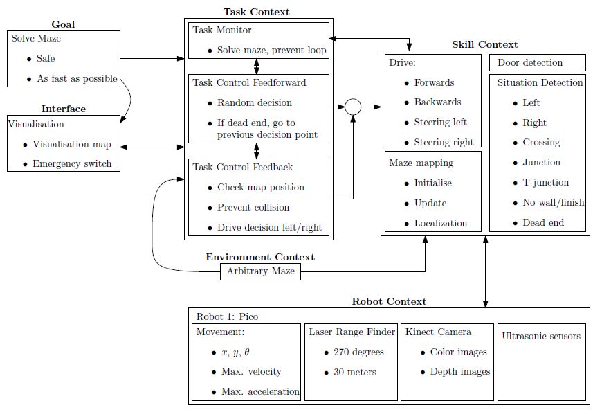
Figure 1.1: Flow chart of the software design

Requirements
The goal of the maze-challenge is to solve the maze as quick as possible and without any collisions. As quick as possible is defined as solving the maze within a minimum amount of steps. The maze can be divided by discrete blocks, so every block is one step in solving the maze. The requirements to fulfill this goal are:
- The robot has to drive, which means movement in the x-, y- and theta-direction.
- The robot has to take boundaries into account to avoid a collision with walls or running into objects.
- The robot has to recognize doors to be able to found the exit of the maze.
- The robot has to be prevented from searching the same area twice, so a map of the maze will be constantly updated to be able to efficiently solve the maze.
Functions
The functions are divided into two groups: the general robot skill functions and the general robot task functions. First the three general robot skill functions are described.
- Drive functions
Realize motion of the robot by providing data to the robots actuators. Realizing the specified motion should be done using a controller to meet the requirements regarding safety.
Input: location set point. Output: motion of robot.
- Detection functions
Characterize different types of corridors based on telemetry provided by the Laser Range Finder.
Input: measured x, y and theta; Output: type of corridor.
- Mapping functions
Updates and maintains a map of the explored maze. These mapping functions can be used to check and visualize the robots actions and set new objectives.
Input: current x, y and theta of the robot; Output: new entry maze map or new robot objective.
Now the three general robot task functions are described.
- Feedback functions
Realize preventing the robot from collisions and check the position in the map to maintain safety requirements and to determine the desired new position in the maze.
Input: current x, y, theta, LFR data and objective; Output: motion of robot.
- Decision functions
Determine which direction or action the robot should take based on the map and current position.
Input: current x, y, theta and position in the map; Output: drive function initiated.
- Monitor functions
Control the exploration of the maze and prevent the robot to explore the same area more than once.
Input: current x, y and theta of the robot; Output: previous unexplored cross
The maze is viewed as a tertiary search tree in which paths represent the branches. Initial path search is done random with no particular preference for a direction and upon hitting a dead end, backtracking is initialized. Backtracking means the robot turns around at a dead end and returns to the previous decision point in the explored maze (map), meanwhile searching for a door. Upon detecting a door or reaching the point of the previous decision the robot continues its random search, or chooses the only unexplored direction at that particular point.
Components
The relevant components in the maze challenge are divided into two parts: the robot itself and the maze as the environment of the robot.
Relevant components of the robot
- Three omniwheels which make it possible to move the robot in x-, y- and theta-direction.
- Laser Range Finder to be able to detect the environment of the robot.
Relevant components of the maze
- Static walls which are the basis of the maze, those walls can form corners, crossings, T-junctions and dead ends.
- Doors which open automatically and make it possible for the robot to get access to the whole maze. Closed doors cannot be distinguished of the wall.
Specifications
Note: Almost all specifications have yet to be determined in specific numbers.
Driving speed specifications
It is unlikely that the maze can be completed with a fixed velocity. Therefore, a number of conditions need to be composed which specify the velocity and acceleration at each encountered situation. Velocity and acceleration may vary on the chosen strategy, for example to find a door (which implies a low velocity or even a drive-stop implementation) or the random walk.
- Random walk to explore an unknown part of the maze.
- Returning from a dead end to the previous decision point, meanwhile searching for a door.
- Detection of an intersection.
- Taking a particular intersection.
Changing direction
The robot can change its direction in different curvatures, at this moment the decision is made to make a full stop before the robot starts rotating. For this action the angular velocity and acceleration need to be specified.
- Determined: make a full stop before changing direction.
- Determined: change direction on a junction when the middle of the junction is reached.
- The angular velocity and acceleration during a rotation need to be specified.
Safety specifications
It is very important that the robot completes the maze without hitting the walls or running into objects. To prevent this, a safety specification should be implemented, which basically comes down to a minimal distance the robot has to maintain to its surroundings.
Laser Range Finder specifications
The Laser Range Finder has a maximal range of 30m. In order to complete the maze successfully, it is expected that this range is too large. The laser range specification to complete the maze has to be determined experimentally.
Interfaces
Regarding the interface, the obtained map from the maze should be visualized for convenient debugging of the code. Paths covered only once should be marked black. In addition, if a given branch does not lead to the exit, the robot will return to the last decision point. The path covered twice due to returning to the last decision point will be marked red.
To prevent unwanted behavior of the robot due to bugs in the software, a kill switch should be implemented in the interface such that the robot can remotely be switched off.