Embedded Motion Control 2015 Group 7: Difference between revisions
| Line 88: | Line 88: | ||
'''Requirements''' | |||
<p>Requirements specify and restrict the possible ways to reach a certain goal. In order for the robot to | <p>Requirements specify and restrict the possible ways to reach a certain goal. In order for the robot to | ||
autonomously navigate trough a maze, and being able to solve this maze the following requirements | autonomously navigate trough a maze, and being able to solve this maze the following requirements | ||
Revision as of 13:22, 21 June 2015
About the group
| Name | Student id | ||
|---|---|---|---|
| Student 1 | Camiel Beckers | 0766317 | c.j.j.beckers@student.tue.nl |
| Student 2 | Brandon Caasenbrood | 0772479 | b.j.caasenbrood@student.tue.nl |
| Student 3 | Chaoyu Chen | 0752396 | c.chen.1@student.tue.nl |
| Student 4 | Falco Creemers | 0773413 | f.m.g.creemers@student.tue.nl |
| Student 5 | Diem van Dongen | 0782044 | d.v.dongen@student.tue.nl |
| Student 6 | Mathijs van Dongen | 0768644 | m.c.p.v.dongen@student.tue.nl |
| Student 7 | Bram van de Schoot | 0739157 | b.a.c.v.d.schoot@student.tue.nl |
| Student 8 | Rik van der Struijk | 0739222 | r.j.m.v.d.struijk@student.tue.nl |
| Student 9 | Ward Wiechert | 0775592 | w.j.a.c.wiechert@student.tue.nl |
03-06: Revised composition pattern.
-->
Introduction

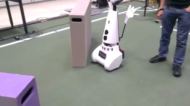
For the course Embedded Motion Control the "A-MAZE-ING PICO" challenge is designed, providing the learning curve between hardware and software. The goal of the "A-MAZE-ING PICO" challenge is to design and implement a robotic software system, which should make Pico or Taco be capable of autonomously solving a maze in the robotics lab.
PICO will be provided with lowlevel software (ROS based), which provides stability and the primary functions such as communication and movement. Proper software must be designed to complete the said goal, the software design requires the following points to be taken in account: requirements, functions,
components, specifications, and interfaces. A top-down structure can be applied to discuss the
following initial points.
Software Design
The software design is discussed in the following subsections. The requirements and functions of the software are listed and two different models are used to characterize the behavior and structure of the software. Note that the actual functionality of the software is not discussed in this section. More detailed information about the individual software functions can be found in [=Software subsystems=]
Requirements
Requirements specify and restrict the possible ways to reach a certain goal. In order for the robot to autonomously navigate trough a maze, and being able to solve this maze the following requirements are determined with respect to the software of the robot. It is desired that the software meets the following requirements:
- Move from certain A to certain B
- No collisions
- Environment awareness: interpeting the surroundins
- Fully autonomous: not depending on human interaction
- Strategic approach
Functions

To satisfy the said requirements, one or multiple functions are designed and assigned to the requirements. describes which functions are considered necessary to meet a specific requirement.
The function ’Build world model’ describes the visualisation of the environment of the robot. ’Path memory’ corresponds with memorizing the travelled path of the robot. ’Sensor calibration’ can be applied to ensure similar settings of both robots, so that the software can be applied for both.
Interface

The interface describes the communication between the specified contexts and functions necessarry to perform the task. The contexts and functions are represented by blocks in the interface and correspond with the requirements, functions, components and specifications previously discussed.
The robot context describes the abilities the robots Pico and Taco have in common, which in this case is purely hardware. The environment context describes the means of the robot to visualize the surroundings, which is done via the required world model. The task context describes the control necessary for the robot to deal with certain situations (such as a corner, intersection or a dead end). The skill context contains the functions which are considered necessary to realise the task.
Note that the block ’decision making’ is considered as feedback control, it acts based on the situation recognized by the robot. However ’Strategic Algorithm’ corresponds with feedforward control, based on the algorithm certain future decisions for instance can be ruled out or given a higher priority.
To further elaborate on the interface, the following example can be considered in which the robot approaches a T-junction: The robot will navigate trough a corridor, in which information from both the lasers as the kinect can be applied to avoid collision with the walls. At the end of the corridor, the robot will approach a T-junction. With use of the data gathered from the lasers and the kinect, the robot will be able to recognize this T-junction. The strategic algorithm will determine the best decision in this situation based on the lowest cost. The decision will be made which controls the hardware of the robot to perform the correct action. The T-junction is considered a ’decision location’, which will be saved in the case the robot is not capable of solving the maze with the initial decision at this location. During the movement of the robot, the walls are mapped to visualise the surroundings.
Composition Pattern

The structural model, also known as the composition pattern, decouples the behavior model functionalities into the 5C’s. The code is divided into five separate roles:
- Computational entities which deliver the functional, algorithmic part of the system.
- Coordinators which deal with event handling and decision making in the system.
- Monitors check if what a what a function is supposed to accomplish is also realized in real life.
- Configurators which configure parameters of the computational entities.
- Composers which determine the grouping and connecting of computation entities.
The total structure is divided into three subsystems which will be discussed individually: movement, detection and strategy.The collaboration between the subsystems is determined by the monitor, coordinator and composer of the main system. Note: the computational entities are discussed in the chapter "Software design".
In the current structure of the code, the three subsystems are combined in the C/C++ main file. This file handles the communication of the various subsystems by using the outputs of the various subsystems as inputs for other subsystems. The different subsystems are scheduled manually. First, the detection subsystem is called to sense the environment and recognize situations/objects. Also, the current location of the robot is determined using the Simultaneous Localization And Mapping (SLAM) algorithm. The strategy subsystem uses this information to make a decision regarding the direction of the robot. This subsystem has a set-point location as output which in turn will be used by the movement subsystem. The movement subsystem uses the current location and the set-point location to control the velocity of the robot. Currently, there is no data logged in the main file. Also, there is no composing happening in the main file.
The detection subsystem is used to process the data of the laser sensors. It's main function is to observe the environment and send relevant information to the other subsystem and the main coordinator. As commissioned by the coordinator the composer simply triggers all computational entities, which are then carried out in the shown order. The computational entities are shortly explained, and further elaborated in the "Software Design".
- Measurement Processing: using Hough transform to convert LFR data to lines and markers.
- Situation Recognition: detecting corners, corridors and doors based on lines obtaing by Hough transform.
- SLAM: creating global coordinate frame in order to localize PICO in the maze.
- World model: gathering recognized situations and corresponding data.
The strategy subsystem is used for path planning. This subsystem receives edge, corridor and door as global coordinate data from the detection subsystem for the computational entities. When the detection subsystem recognizes a situation in the maze a discrete event is send to the coordinator of this system which will then triggers all computational entities via the composer. These then choose the best path to take, which is executed by the Movement subsystem. To perform accordingly, the following computational entities are designated:
- Node network: network containing all corners and junctions.
- Tremaux: determines which direction to choose at junctions.
- Path Memory: memorizes visited locations, sends information as discrete location data to world model.
Based on the computational entities a planned path is determined. This path is send to the monitor, together with the Point-to-point movement coordinater from the Movement subsystem. The monitor is applied to check whether or nor the path is followed as is desired.
The movement subsystem controls the movement of the robot, based on the input it receives from the other subsystems of the robot. The movement receives the current position of the robot, determined by the SLAM algorithm in the detection subsystem, together with the set point location, determined by the strategy subsystem, both in a global coordinate system. The movement subsystem calculates the robot velocity (in local x, y and theta-direction) so the robot will move from the current location (A) to to the set-point location (B), while avoiding collisions with object. To this end, three compu- tational entities are used.
- Non-linear controller: controlling x and theta velocity.
- Velocity profile: predescribing acceleration and maximum velocity
- Potential field: redirecting PICO for objects in the near proximity
Note that the configurator predescribes the maximum velocity, operating based on events raised by other subsytems. The monitor should assure that PICO arrived at the set-point location, otherwise raising an event to act on accordingly.
Software subsystems
[new intro following on 27-05 wrt new structure and subsystems: movement, detection, strategy]
Detection
The initial idea of edge detection will be replaced by a set of multiple detection methods: Hough Transform and SLAM. At this point edge detection is still in use, this will be become a part of the Hough Transform code.
Edge detection
An edge can be considered as a discontinuity of the walls perpendicular to the travel direction of PICO. This can be either an door (open/closed), a corner or a slit in the wall. At this stage only the detection of a corner will be implemented.
.
The edge is then defined as the position of the corner (relative to PICO). At every (time)step the relative distances (wall to pico)will be checked, based on LRF data. If at some point the distance between one increment of the LRF and the neighbouring increment exceeds a certain treshold, it can be considered as an edge point. This is further illustrated by the image. This primary idea is however not robust, therefore the average of neigbouring increments is checked. Robustness will be further improved later on.
Hough Transform

The Hough transformation is used to detect lines using the measurement data. The basic idea is to transform a single point into the parameter space of the set of infinite lines running through it, called the Hough space. In the polar coordinate system of the laser scan, a line through a data point is given by [math]\displaystyle{ \rho=d\cos(\alpha-\phi) }[/math] where [math]\displaystyle{ \rho }[/math] is the length of the orthogonal from the origin to the line and [math]\displaystyle{ \phi }[/math] is its inclination.
By varying [math]\displaystyle{ \phi }[/math] for each data point from 0 to 180 degrees, different [math]\displaystyle{ (\rho,\phi) }[/math] pairs are obtained. Laser points which are aimed at the same wall will yield the same [math]\displaystyle{ (\rho,\phi) }[/math] pair. To determine if a given [math]\displaystyle{ (\rho,\phi) }[/math] pair is a wall, [math]\displaystyle{ \rho }[/math] is discretized, and a vote is cast at the corresponding element for that [math]\displaystyle{ (\rho_d,\phi) }[/math] pair in an accumulator matrix. Elements with a high number of votes will correspond with the presence of a wall. The end-points of the walls are found using detected corners and the intersection points of the walls.
SLAM
For localisation and mapping, the Extended Kalman Filter is used. The own made algorithm can be divided into two parts. In the first part the founded markers, in our case corners, are used to make a prediction of the position of the robot (x,y,theta) and the markers (x,y). In the second part the robot is driving through the environment and gets information. The found markers must be associated with already found markers our must be saved as new markers. With the extended Kalman filter the positions of the robot and found markers are updated.
Prediction problem
The prediction is made with use of the already found corners. These are translated to the global coordinates and the positions are stored in a vector. As initial guess, the odometry data is used to predict how far the robot has moved compared with the last time. Also the covariance matrix is determined to predict how accurate the measurements are. The values for the amount of noise of the measurements must be tuned during experiments.
Association problem
When the robot is driving through the maze, every loop there is a possibility that there are corners detected. For each of these corner, there must be found out If these corners are already detected, our are not saved yet. For now, there is chosen to make a finding area of 20cm by 20cm where is looked in based on the prediction. So there is made an estimation where the markers should be and these are compared with the found markers. When the difference in lower than our chosen reference, the marker is found again. When the marker is found again, the position of the marker is updated with use of the Kalman filter and the same is done for the position of the robot. The vector with the position of the robot and marker can be used to make a world map. The robot can be positioned in this map.
Strategy
The Strategy consists of two plant, the initial plan and the final plan as used during the Maze challenge.
Initial Plan
The initial strategy plan is dependant of the SLAM and Detection part of the code. It consists of a Tremaux algorithm which is provided with a highest succes rate decision maker, a pathplanner and a Dijkstra algorithm to determine the shortest path.
Tremaux describes the placing of landmarks and the (random) order selection of certain choices which can be made by PICO, in this case which path to continue at i.e. an intersection. The highest succes rate decision maker is applied to remove the randomness in the Tremaux algorithm, the direction of the intersection with the least side branches is most preferred (it has the most chance of being successful).
The pathplanner is used to process all the landmarks placed by the Tremaux algorithm into a matrix, describing all possible connections and costs (in this case distance) between nodes. The Dijkstra algorithm will determine the lowest distance of unvisited node, connected to a certain starting node. All possibilities will be stepwise determined, updating the most proferred path from start to end. At the end of the strategy process an array will result, describing all necessary landmarks PICO should move to in order to reach the end.
Change of Plans
As earlier discussed, SLAM is not working robustly as desired, rotation of PICO leads to insufficient results. Since the original plan of Strategy was highly dependant on both the overall Detection as SLAM, a change of tactics is necessary. The alternative plan will not make use of SLAM, and therefore the strategy lacks the presence of certain map. As a result , some issues will occur in specific occasions. These issues will be tackled individually, the main goal in this stage of the project is a PICO actually capable of finishing the Maze challenge.
Due to the absence of SLAM and the map, the Tremaux and Dijkstra algorithms can not be used as initially planned. The strategy will now consist of a " switch", capable of switching between the Homing and the action as decided by the decision maker. Detection will detect a i.e. a deadend or junction, raising their corresponding integer. This integer will trigger a specific decision maker in Strategy based on the situation PICO has recognized. Detection will also determine the open side branches, usefull for the orientation of the T-junction.
If PICO would recognize a junction, a position in which in certain choice has to be made, the decision maker is triggered. The decision is predescribed and depends on the value of the previous " action" of PICO. If PICO would have made a certain decision at a junction, and this choice was unsuccesfull, it will return to the same junction and the " action" is updated. In this way, PICO will analyse every choice in a structured manner. If during a certain choice PICO would again recognize a junction this means that this choice is in some way succesfull, therefore the " action" is resetted. For the T-junction and cross junction to following actions are predescribed:
- Cross junction: 1: "go right", 2: "go straight", 3: "go left" and 4: "go straight"
- T-junction: 1: "go right" and 2: "go straight"
For the T-junction this will mean that the action is automatically updated if the desired direction as predescribed by the action schedule set is not possible (hence not open). This method us somewhat cumbersome and time demanding, but should make PICO capable of finishing the maze.
Movement
The "movement" part of the software uses data gathered by "detection" to send travel commands to PICO. In the near future, a new "strategy" part of the software will be designed, which basically becomes the "decision maker" which commands the "movement" of PICO. An odometry reset has been implemented to make sure that the code functions properly every time PICO starts in real life.
The current non-linear controller has some sort of stiffness, which results in PICO slowing down too soon too much. This “stiffness” can be removed, so it just goes full speed all the time, but this is a bad idea. Due to the sudden maximum acceleration and deceleration which might result in a loss of traction, the odometry data could get corrupted and therefore the movement would not work properly. Instead, a certain linear slowing down is introduced when PICO comes within a certain range of its destination. It also slowly starts moving from standstill and linearly reaches its maximum velocity, based on a velocity difference.
Local coordinates

The main idea is to work with local coordinates. At time t=0, coordinate A is considered the position of PICO in x, y and theta. With use of the coordinates of edges received by "detection" point B can be placed, which decribes the position PICO should travel towards. This point B will then become the new initial coordinate, as the routine is reset. In case of a junction as seen in the figure multiple points can be placed, allowing PICO to choose one of these points to travel to.
The initial plan is to first allow PICO to rotate, followed by the translation to the desired coordinates. This idea was scrapped, because this sequence would be time consuming. Instead a non-linear controller was used, that asymptotically stabilizes the robot towards the desired coordinates.
Although the PICO has an omni-wheel drive platform, it is considered that the robot has an uni-cylce like platform whose control signals are the linear and angular velocity ([math]\displaystyle{ u }[/math] and [math]\displaystyle{ \omega }[/math]). The mathematical model in polar coordinates describing the navigation of PICO in free space is as follow:
- [math]\displaystyle{ \dot{r}=-u \, \text{cos}(\theta)\! }[/math]
- [math]\displaystyle{ \dot{\theta}=-\omega + u\, \frac{\text{sin}(\theta)}{r},\! }[/math]
where are [math]\displaystyle{ r }[/math] is the distance between the robot and the goal, and [math]\displaystyle{ \theta }[/math] is the orientation error. Thus, the objective of the control is to make the variables [math]\displaystyle{ r }[/math] and [math]\displaystyle{ \theta }[/math] to asymptotically go to zeros. For checking such condition, one can consider the following Lyapunov function candidate: [math]\displaystyle{ V(r,\theta) = 0.5 \, r^2 + 0.5 \, \theta^2 }[/math]. The time derivative of [math]\displaystyle{ V(r,\theta) }[/math] should be negative definite to guarantee asymptotic stability; therefore the state feedback for the variables [math]\displaystyle{ u }[/math] and [math]\displaystyle{ \omega }[/math] are defined as,
- [math]\displaystyle{ u = u_{max}\, \text{tanh}(r)\, \text{cos}(\theta) \! }[/math]
- [math]\displaystyle{ \omega = k_{\omega} \, \theta + u_{max} \frac{\text{tanh}(r)}{r} \, \text{sin}( \theta) \, \text{cos}( \theta),\! }[/math]
where [math]\displaystyle{ u_{max} }[/math] and [math]\displaystyle{ k_{\omega} }[/math] both are postive constants.
Potential field

If PICO would be located at position A and would directly travel towards point C, this will result in a collision with the walls. To avoid collision with the walls and other objects, a potential field around the robot will be created using the laser. This can be interpreted as a repulsive force [math]\displaystyle{ \vec{U} }[/math] given by:
- [math]\displaystyle{ \vec{U}(d_l) = \begin{cases} K_0 \left(\frac{1}{d_{pt}}- \frac{1}{d_l} \right) \frac{1}{{d_l}^2} & \text{if } d_l \lt d_{pt}, \\ ~~\, 0 & \text{otherwise}, \end{cases} }[/math]
where [math]\displaystyle{ K_0 }[/math] is the virtual stiffness for repulsion, [math]\displaystyle{ d_{pt} }[/math] the range of the potential field, and [math]\displaystyle{ d_l }[/math] the distance picked up from the laser. Moreover, the same trick can be applied in order for an attractive force
- [math]\displaystyle{ \vec{V}(d_l) = \begin{cases} 0 & \text{if } d_l \lt d_{pt}, \\ ~~\,K_1 d_{l}^2 & \text{otherwise}, \end{cases} }[/math]
where [math]\displaystyle{ K_1 }[/math] is virtual spring for attraction. Summing these repulsive force [math]\displaystyle{ \vec{U} }[/math] results into a netto force,
- [math]\displaystyle{ \vec{F}_n = \sum_{i=1}^N \vec{U}(d_{l,i}) + w_i\vec{V}(d_{l,i}), }[/math]
where [math]\displaystyle{ N }[/math] is the number of laser data, and [math]\displaystyle{ w }[/math] a weight filter used to make turns. Assume that the PICO has an initial velocity [math]\displaystyle{ \vec{v_0} }[/math]. Once a force is introduced, this velocity vector is influenced. This influence is modeled as an impulse reaction; therefore the new velocity vector [math]\displaystyle{ \vec{v}_r }[/math] becomes,
- [math]\displaystyle{ \vec{v}_r = \vec{v_0} + \frac{\vec{F}_n \,}{m_0} \, \Delta t, }[/math]
where [math]\displaystyle{ m_0 }[/math] is a virtual mass of PICO, and [math]\displaystyle{ \Delta t }[/math] the specific time frame. The closer PICO moves to an object, the greater the repulsive force becomes. Some examples of the earlier implementation are included:
 |
 |
Maze challenge
During the maze challenge, the performance of PICO was not satisfactory as it wasn't able to reach the door, let alone solve the move. During the final testing before the challenge, it was already clear that the detection part of the code did not gave the desired results in real life, which is contrary to the simulation where it worked fine. This is caused by the fact that in real life, the incoming laserdata is not so nicely received by PICO due to diffuse reflectance of the walls, opposed to in the simulation where the walls are 'smooth'. The robot did not recognize situations properly because apparently the code was not robust enough to deal with this. To try to make it work, some tolerances were changed. However, during the first try of the maze challenge, PICO started rotating too early or kept rotating because the detection was still not good enough. This made PICO think it was at a junction all the time and that it had to take action, i.e. make a turn.
For the second try, a different code was used with other detection parameters. This time, PICO did a better job at recognizing the situations, but still not satisfactory. It failed to recognize the T-junction of the door, after which it came to a halt at a corner. Stuck in its place, it did not move anymore which finished the try. The fact that it did not move anymore might be because of the used potential field which was used to drive. The input command for driving was very low when it got stuck. The potential field did not have an integrator action to give it a high value when standing still. With the low drive input, the motors did not gain enough power to overcome the static friction, resulting in PICO being stuck in one place.
Overall conclusion
What for us what noticable, is the fact that PICO worked fine up to the final test, the day before the maze challenge. It could detect situations and move nicely through our small test-mazes. However, when we put everything together it did not do what we intended it to do. In the end, we think we bit off more than we could chew. At the start of the project we decided to use SLAM to create a world model and based on that we would use Tremaux's alghorithm to solve the maze. We wanted to make everything ourselves and not just simply copy already existing code so we would understand what is happening. However, it proved that SLAM was hard to realize and that creating our own Hough-lines algorithm was no easy task either. Furthermore, the overall code structure kept changing during the project to match the composition pattern, which step after step kept improving. After it had been decided that it would be too risky to rely on SLAM, as it might or might not work, a simpler strategy was used and there would be no mapping of where the robot has been. The main focus was shifted to creating a clear code structure. However, the switch to the simpler plan was made too late to produce a robust code for PICO to solve the maze.
Another challenge during the entire project was our group size. We noticed it was important to keep good communication, something which was difficult and not always achieved. We experienced that the reality is different from the simulation and if we had more testing time, we might have altered the code such that the results were satisfactory. We also learned that first determining a good overall code structure and sticking to it is key. We did change the structure a lot, but we are proud of it now. Another thing we are proud of, is the fact that we wrote everything ourselves, even if it was not used eventually, like SLAM.