Embedded Motion Control 2015 Group 6: Difference between revisions
| Line 193: | Line 193: | ||
[[File:InitialAlgorithm.JPG|center]] | [[File:InitialAlgorithm.JPG|center]] | ||
== Features of the Software == | |||
=== Collision Detection === | |||
=== Position Alignment === | |||
=== Find the Gap === | |||
Revision as of 18:12, 28 May 2015
Group Members
| Name: | Student id: | E-mail: |
| Akash Agarwal | 0923269 | a.agarwal@student.tue.nl |
| Angus Pere | 0926353 | a.f.pere@student.tue.nl |
| Ashish Yadav | 0925559 | a.yadav@student.tue.nl |
| Floris Remmen | 0920072 | f.remmen@student.tue.nl |
| S. Cagil Mayda | 0926975 | s.c.mayda@student.tue.nl |
| Ugonna Mbaekube | 0927006 | u.o.mbaekube@student.tue.nl |
| René van de Molengraft | Tutor | m.j.g.v.d.molengraft@tue.nl |
Planning
Week 1: 22 April - 29 April
- Introduction lecture
- Meeting 1: Initial design document & C++ tutorials
- Ubuntu and other required softwares Installation
Week 2: 29 April - 6 May
- 27-04 12:00: Deadline initial design
- Finishing C++ tutorials
- Start studyin maze algorithms
- Meeting 2: Division of team roles in the project
- Reading tutorials
- Prepare presentation
Week 3: 4 May - 10 May
- 6 May: First presentation of the design
Week 4: 11 May - 17 May
- 13 May: Corridor competition
Week 5: 18 May - 24 May
- Lecture 3: Composition Pattern part II by Herman Bruyninckx
Week 6: 25 May - 31 May
- 27 May: Second presentation of the design
Week 7: 1 June - 7 June
- Lecture 4: Communication patterns
Week 8: 8 June - 14 June
- 10 June: Presentation of final design
Week 9: 15 June - 21 June
- 17 June: Final competition
Update Log
Initial Design
Goal
The goal of the “A-Maze-ing challenge” is to design and implement a software for the PICO robot to navigate through a maze autonomously while optimizing time.
Requirements
To program a PICO robot to participate in the “A-Maze-ing challenge”, it is desired that the software meets the following requirements.
- The PICO robot should be able to navigate through any maze autonomously regardless of its configuration. (Autonomous Behaviour)
- The PICO robot should be able to avoid all obstacles during its navigation through the maze including contact with the walls of the maze.(Collision Avoidance)
- The PICO robot should never get “stuck” at any position in the maze and should make desired movements.(Movement)
- The PICO robot should be able to make use of its sensors to navigate the maze.(Use of Sensors)
- The PICO robot should have some sort of “memory” that prevents it from moving back towards paths already navigated through.(Awareness of the environment)
- The PICO robot should be able to find the optimal path through the maze while optimizing time.(Optimal Path Calculation)
- After navigating through the maze, the PICO robot should be able to autonomously terminate its movement.(Termination)
Functions
The basic functionality of the robot that are assigned to requirements in order to reach the goal are as follows:
1) Drive
- Move Forward
- Move Backwards (Reverse)
2) Obstacle & Wall Detection
- Calculation of Distance to objects
3) Decision Making
- Turn Left/Turn Right
- Rotate
- Termination of movement on completion of the maze
4) Optimal Path Algorithm
- “Memory” storage
- Localisation
Components and Specificications
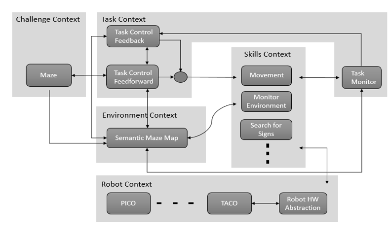
Initial Schematic overview of the components to be used in the software design
1) Task Context: Controls the implementation of the robots functions depending on the challenge and environmental context.
- Task Monitor: Monitors the implementation of the robots functions and sends the information to the task control feedback.
- Task Control Feedback: Implements control action on the robot based on information received from the task monitor.
- Task Control Feedforward: Contributes in the implementation of control actions on the robot depending on the state and the goal of the challenge.
2) Environmental Context: Semantic maze model.
3) Challenge Context: All information regarding the rules and the goals of the “A-Maze-ing challenge” are stored in this context.
4) Robot Context: This incorporates the low level specifications of the PICO robot.
5) Skills Context: Contains the above mentioned robot functionalities.
Interfaces
1) Challenge Context – Environmental Context: deals with presumptions about the maze and goal methodology.
2) Skill Context- Robot Context: deals with sending commands to the low-level hardware.
3) Task Context- Environmental Context: provides information to the task context about decisions to be made in the maze.
4) Challenge Context- Task Context: provides the aim of the challenge context to the task context in order for the task context to adhere to the rules of the game while decision making.
5) Task Context – Skill Context: Allocates the necessary skill dependent on the contribution of the task control feedforward and feedback.
Design Updates
Corridor Competition
For this competition, it was aimed to exit the corridor succesfully with an easy approach.
Hardware Components
- Laser Data: Observations will be written.
- Odometry Data: Observations will be written.
Initial Software Design
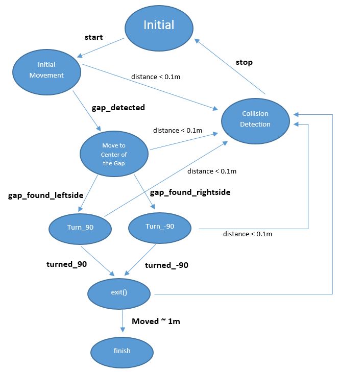
- Initial Movement: Robot starts with a constant speed and move forward through the corridor.
- Collision Detection: With using the laser data, distance to the wall or any other obstacles (no obstacles in this case) can be determined. If the distance becomes less than 0.1 metre, robot will stop to avoid collision.
- Position Alignment: It is observed that, due to feature of omni wheels, robot sometimes can not go straight. So in the algorithm, Pico is forced to stay in the middle of the corridor by calculating the distance to the right and left wall by using laser data.
- CheckCorridor: Robot will constantly check the distances to the left and right wall. If the distance to one of them exceeds the threshold (max.width has already known) turn left/right command will be executed.
- Turn Left/Right: After robot moves in the middle of the gap, it turns +/-90 degrees by using the odometry data. When it is turned, it again starts moving forward.
- Finish: Since the distance to finish can be approximated, after moving some distance, robot will stop automatically.
States of the initial design can be seen in the following figure:

