Embedded Motion Control 2015 Group 1
Embedded Motion Control (EMC) Group 1 is a multidisciplinar and multilingual project group working on the 'A-MAZE-ING PICO'. This wikipedia page consists of the weelky progress presented in the journal, the written report and some other practical and useful stuff.
The report focussus on the individual components of the software architecture, this includes basic idea description, mathematical analyses and possible software implementation.
Journal
The proces of developing a software architecuter and the implementation requires great coordination and collaboration. This journal will be updated to present and track the progress of the group. This journal includes weekly progress, countered problems and divided tasks.
Meetings
1. Thursday 23: 12:45 - 13:30 in OGO19
2. Wednesday 29: 10:15-11:00 in OGO17
3. Friday 1 May: ?-? in ?
Design Architecture

In this section, the initial idea of an embedded software design will be discussed. The main goal of the design is to make the Pico robot able to solve a maze. In this brief report, the requirements, functions, components specifications, and the interfaces of such a system will be discussed.
Requirements
The requirements of the system will be divided according to the FURPS model. The abbreviation of this model stands for Functionality, Usability, Reliability, Performance, and Supportability. Functionality in this case denotes the features and capabilities of the system. Usability includes the human factors, consistency, and aesthetics. Reliability stands for the failure frequency, accuracy, predictability, et cetera. Performance here means the efficiency, speed, response, i.e. measures of system performance. Finally, the supportability incorporates testability, maintainability, configurability, and so forth.
The main requirement of the system will be to navigate the maze. It must be completed according to the challenge specification, which forms the main functional aspect of the requirements.
Furthermore, the system design must be robust. The layout of the system must constitute all possible functions to account for the various system architecture, which enable the usability of that design. To achieve this, possible fault modes can be taken into account.
Also, the system design should pose a robust solution. This means the provided system solution must be robust enough to cope with the environmental uncertainties, so that the solution as a whole is reliable.
Next, the doors in the maze should be handled correctly. The behaviour of the door should be analysed to help differentiate the door from the wall. Firstly, the robot should be able to recognize a door from a wall and, secondly, cross the door.
Fifthly, the generated design should be tested for its reliability, and accordingly changes are required to be captured to improve the same.
Furthermore, The major functional requirement of the robot is the ability to solve the maze on its own.
Next, the given hardware (PICO robot) must be used for the maze challenge without any modification and additional components mounted on it.
Penultimately, the performance requirement of taking quick decision is one of the essential factors for the PICO robot for completing the challenge within 7 minutes.
And finally, the need for smart decision making is a crucial necessity due to the fact that the environment changes.
In the table below, the above requirements are summarized according to the FURPS structure.
| Requirement | F | U | R | P | S |
|---|---|---|---|---|---|
| Navigate the maze | x | ||||
| Subsystem based design | x | ||||
| Adaptable to environment | x | ||||
| Door handling | x | ||||
| Testing and simulation | x | ||||
| Autonomous operation | x | ||||
| Use given hardware | x | ||||
| Fast decision making | x | ||||
| Smart decision making | x |
Functions
The functions of the system are classified according to three levels: high-level, mid-level, and low-level functionalities.
The high-level functionality incorporates the following three aspects:
- Obtain relative position with respect to the global frame of reference in the maze.
- Identification of the open or closed door.
- Maze solving algorithm or strategy.
The mid-level functionality consists of:
- Straight corridor navigation.
- Collision avoidance algorithm.
- Intersection mapping.
The low-level functionality contains:
- The ability to read the laser and camera input.
- Actuate the wheels according to the input.
- System initialization for the working of the sensors and actuators.
Components
To obtain a clear overview of the system, its architecture is shown in the figure above, including its various components.
Specifications
The specifications of the system are formed by the available hardware and software, and by some of the requirements for the challenges.
- Limited time to complete the maze challenge (7 min).
- Limited access to the actual PICO robot.
- Robot hardware is not to be modified.
- Hardware access is facilitated via ROS.
- Translational/rotational speed limit of the robot actuators.
- Use of C++ and SVN.
- Available sensors: Kinect and laser.
- Use of controller feedback.
- Unknown location of entrance and exit on the boundary of the maze.
Interfaces
Within the system, two types of interfaces are distinguished. First, there is the communication between the different components of the system, shown in the figure above as arrows. The second type of interface, is the interface on which the robot interacts with the environment. This includes a user interface to program the robot, and sensors to sense the environment. There is no user interface to communicate with the robot while it is solving the maze, for it is autonomous. The sensors used by the robot are discussed in the specifications.
Potential Field
Report-like explanation of the potential field: the working principle, the underlying mathematics and, the implementation.
Lower Level Skills
Drive Skills
It is based on the information from the Potential Field. The driving instructions sent to the motors is related to the "wall rejection force vectors".
Safety Layer
The first safety measure is the potential field algorithm itself. It's very nature should prevent the robot to getting too close to the walls. However, looking for completeness and having safety redundancies in the code, another safety routine was implemented. The basic idea is to prevent the robot to hit the walls, so the distance to the walls is continuously compared to a safety margin. If the distance is smaller the robot will stop and enter a routine that should take the robot away from the wall and put the robot in place to keep driving safely.
Turn Skill


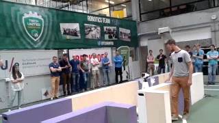
Corridor Challenge
Preparation of the Embedded Motion Control #Corridor Competition and the results shown in a short movie.
- Available Approaches
Based on the results from the test run with the real robot, the following solutions were proposed: Robust Turning. Safe or Fast modes. Simple Turns. Hard-coded turns.
A relevant concept in the development of the solutions was to be able to identify that the robot was turning and not only turn as an extension of "regular corridor driving". As a result, a simple state machine was implemented. It modifies the decision making of the robot as long as it recognizes to be in a turn.
 |
- Results
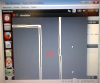
The driving through the straight part of the corridor was smooth and fast reactions were not evident. Just as in the simulation shown previously, the robot detected the side exit appropriately.
 |
The separation of the turning action into states is meant to facilitate the implementation of higher level navigation afterwards. After the challenge some new scenarios were tested to gain some insight of the robustness of the code. First, a small separation between the wall-blocks. Second, narrower corridor. And finally, remove the side exit walls to check if the robot could still recognize it, turn and stop. From these new scenarios, the results were as follow: 1) the code is able to navigate well even is some discontinuities exist in the walls, 2) The robot can drive through the corridor regardless of it having a different width, however, if the width is smaller than the safety margin established in the code, the robot will not move. And 3) Even if the side-corridor has no walls the robot was able to recognize it, turn and stop. These tests show that the robust approach can deal with an uncertain environment up to this level.
- Analysis
Appendix
The Appendix consists of the unrelevant parts of the report. This includes a list of the group members and some tips and tricks for programming.
Group members
Group 1 consists of the following members:
| Name | Student nr | |
|---|---|---|
| Maurice Poot | 0782270 | m.m.poot@student.tue.nl |
| Timo Ravensbergen | 0782767 | t.ravensbergen@student.tue.nl |
| Bart Linssen | 0786201 | a.j.m.linssen@student.tue.nl |
| Rinus Hoogesteger | 0757249 | m.m.hoogesteger@student.tue.nl |
| Nitish Rao | 0927795 | n.rao@student.tue.nl |
| Aakash Amul | 0923321 | a.v.h.amul@student.tue.nl |
| Ignacio Vazquez | 0871475 | i.s.vazquez.rodarte@student.tue.nl |
Qt from terminal
If Qt Creator is not run from the terminal, the programs inside cannot connect to the ROS master. To be able to run Qt Creator from the desktop without any problems, follow a similar procedure to the one that is used in the Customizing Ubuntu tutorial for the Terminator file:
Edit
~/.local/share/applications/QtProject-qtcreator.desktop
and change the third line to:
Exec=bash -i -c /home/rinus/qtcreator-3.3.2/bin/qtcreator
This will run QtCreator from a terminal even if the desktop icon is used.