Embedded Motion Control 2014 Group 8
Harm van Deursen
Lex Hoefsloot
Paul Verhoekx
Teun Melief
Robin Smit
PICO Knowns
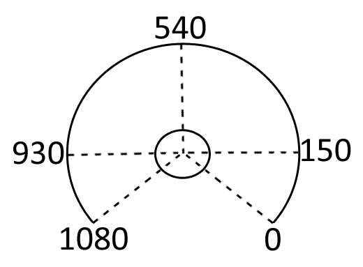
1. 1080 laser points for distance measurement
2. approximately 250 degrees of measurement direction
3. The datapoint at the left (930), front (540) and right (150)
4. The maximum distance measurement is 30 meters
5.
The figure on the right shows the location of the laser (distance) measurement points
First test
The first goal was to survive the corridor test. This means any corner, left or right, should be detected and taken without any collosion.
There were two main tactics to be tested;
Global tactic (inserted in both programs):
- The corner can be detected by either laser point #150 or #930.
- Safety (not hitting the wall) is inserted for the measurement points 150 - 250, 400 - 540, 540 - 680 and 820 - 970.
first tactic:
1. The distance in front is measured and saved when a corner is detected.
2. Than PICO starts rotating until the distance on the side where the corner has not been measured is equal to the distance that was previously in front
3. PICO drives sidewards until the distance is 30 centimeters less
4. pico drives straight ahead again. The corner is taken
Second tactic:
1. The corner is measured but PICO keeps on driving straight ahead and the timer starts
2. The end of the corner is detected and the timer stops
3. PICO drives backwards for half of the time the timer has measured
4. PICO drives sidewards through the corner
5. PICO turns to get back in its neutral position
Observations;
- All measurement points should be used for safety to ensure safety
- The big mess should be cleaned and divided into seperate files which will be included into the master file
- One point to measure a corner is not robust. This should be done by the use of more points.
However, the second tactic seems to work quite okay and will thus be used for the corridor competition
Corridor test
second test
Approach
Two approaches are investigated. The basis of both is to drive safe. Save driving is interpretated as "not hitting the walls". This is implemented as follows: if the laser scans a wall... TODO.
Now the robot does not hit any walls, the first approach can be implemented. This approach is "time-based": Pico drives between the walls. If the lasers scan a gap at the right or the left the program measures the time. Meanwhile, pico is still driving forward and is still measuring the opening. If the lasers scan a wall again, pico measures the time again. Now the time to drive from the beginning of the opening to the end of the opening is known, so also the time to drive to the middle of the opening is known. This is exactly the time pico needs to drive backwards. Now pico is driving sidewards for a specific amount of time (this time needs to be tuned). Now the robot is in the "new" corridor. The last action is to turn 90 degrees. This is done by driving a specific amount of time (dependent of the turningvelocity).
SCHEME NEEDS TO BE INCLUDED
The second approach...
Role division
driving, arrow detection, trajectory planning...
It's a new world
How to load the T-junction:
- Open Terminator
- Run:
gazebo maze/placearrow_Tjunc.world
when in the maze folder - In another terminal
- Run:
rosrun maze spawn_Tjunc
- and run:
roslaunch pico_gazebo pico.launch
to load Pico - Now you can run Rviz:
rosrun pico_visualization rviz
