Embedded Motion Control 2014 Group 2
Members of Group 2:
Michiel Francke
Sebastiaan van den Eijnden
Rick Graafmans
Bas van Aert
Lars Huijben
Planning:
Week1
- Lecture
Week2
- Understanding C++ and Ros
- Practicing with pico and the simulator
- Lecture
Week3
- Start with the corridor competition
- Start thinking about the hierarchy of the system (nodes, inputs/outputs etc.)
- Dividing the work
- Driving straight through a corridor
- Making a turn through a predefined exit
- Making a turn through a random exit (geometry unknown)
- Meeting with the tutor (Friday 9 May 10:45 am)
- Lecture
Week4
- Finishing corridor competition
- Start working on the maze challenge
- Think about hierarchy of the system
- Make a flowchart
- Divide work
- Corridor challenge
Week5
- Continue working on the maze challenge
Week6
Week7
Week8
Week9
- Final competition
Summary:
Corridor Challenge
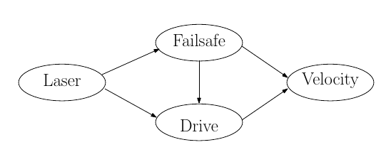
The system for the corridor challenge is made up from 2 nodes. The first one is a very big node which does everything needed for the challenge, driving straight, look for corners, turning, etc. The second one is some kind of fail-safe node which checks for (near) collisions with walls and if so, it will override the first node to prevent collisions. The figure next to the ros-node overview displays the internal functions in the drive-node.
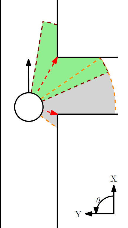
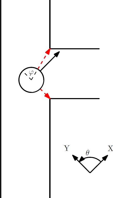
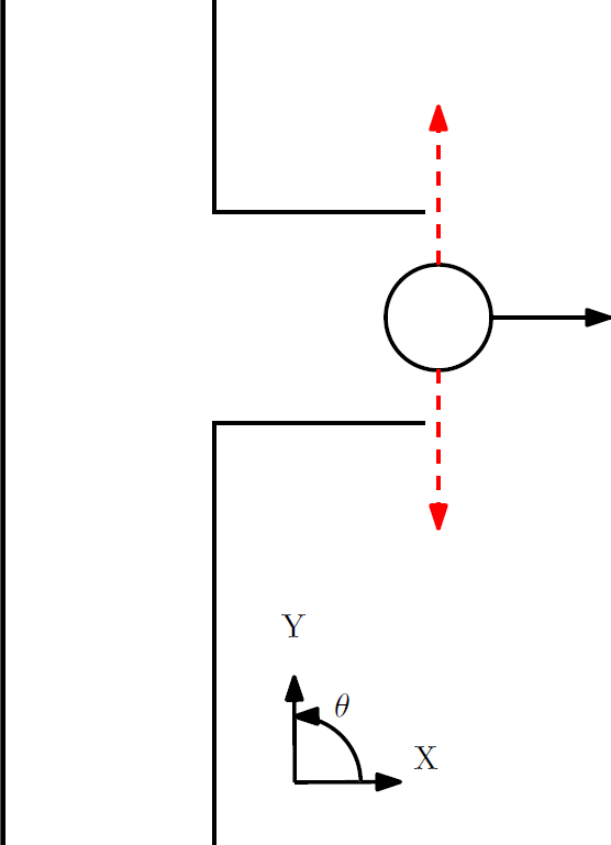
Each time the LaserCallBack function gets called the CheckWalls function is called in it. This function looks at the laser range at -pi/2 and pi/2. If both the lasers are within a preset threshold it sets the switch that follows the CheckWalls function such that it will execute the Drive_Straight function. If either the left or the right laser exceed the threshold it will cause the switch to execute the Turn_Left or Turn_Right function respectively. If both lasers exceed the threshold pico must be at the exit of the corridor and the stop function is called. Each of these functions in the switch set the x,y and z velocities to appropriate levels in a velocity command which can then be transmitted to the velocity ros-node.
Time Survey Table 4K450
| Members | Lectures [hr] | Group meetings [hr] | Mastering ROS and C++ [hr] | Preparing midterm assignment [hr] | Preparing final assignment [hr] | Wiki progress report [hr] | Other activities [hr] |
|---|---|---|---|---|---|---|---|
| Week 1 | |||||||
| Lars | 2 | 0 | 0 | 0 | 0 | 0 | 0 |
| Sebastiaan | 2 | 0 | 0 | 0 | 0 | 0 | 0 |
| Michiel | 2 | 0 | 0 | 0 | 0 | 0 | 0 |
| Bas | 2 | 0 | 0 | 0 | 0 | 0 | 0 |
| Rick | 2 | 0 | 0 | 0 | 0 | 0 | 0 |
| Week 2 | |||||||
| Lars | 2 | 0 | 16 | 0 | 0 | 0 | 0 |
| Sebastiaan | |||||||
| Michiel | 2 | 0 | 8 | 0 | 0 | 0 | 0 |
| Bas | |||||||
| Rick | |||||||
| Week 3 | |||||||
| Lars | 2 | 0.25 | 4 | 13 | 0 | 0 | 0 |
| Sebastiaan | |||||||
| Michiel | 2 | 0.25 | 6 | 2 | 0 | 0 | 0 |
| Bas | |||||||
| Rick | |||||||
| Week 4 | |||||||
| Lars | |||||||
| Sebastiaan | |||||||
| Michiel | |||||||
| Bas | |||||||
| Rick | |||||||
| Week 5 | |||||||
| Lars | |||||||
| Sebastiaan | |||||||
| Michiel | |||||||
| Bas | |||||||
| Rick | |||||||
| Week 6 | |||||||
| Lars | |||||||
| Sebastiaan | |||||||
| Michiel | |||||||
| Bas | |||||||
| Rick | |||||||
| Week 7 | |||||||
| Lars | |||||||
| Sebastiaan | |||||||
| Michiel | |||||||
| Bas | |||||||
| Rick | |||||||
| Week 8 | |||||||
| Lars | |||||||
| Sebastiaan | |||||||
| Michiel | |||||||
| Bas | |||||||
| Rick | |||||||
